Post-Deployment Audit: Flow Field Design and Thermal Management in Large-Format PEM Cells
Executive Summary
The GrInHy2.0 project at Salzgitter Flachstahl --- 720 kW of Sunfire SOEC electrolysis at 850 degrees C, FCH JU funded, the largest solid oxide electrolyser demonstration in Europe at the time --- documented something the project team described carefully in its published reports: during early testing phases, strong thermal gradients and suspected loss of electrical contact created performance issues that required fast current control strategies and insulated edge sealing to mitigate in later module generations. The mean degradation rate in well-managed modules was under 23 mOhm.cm²/kh. The lesson the GrInHy2.0 team drew was explicit: thermal gradient management is the primary scaling challenge for large-format electrochemical cells, and it must be explicitly designed for rather than assumed to follow prototype behaviour. Published PEM electrolyser studies confirmed the same finding: Z-type manifolds produce 3--4x worse flow distribution than U-type manifolds for channels longer than 400 mm, and the pressure drop non-uniformity scales approximately as the square of the channel length. Infrared thermography studies had already demonstrated that once peak-to-mean current density ratio exceeded 1.20, hotspot membrane lifetime was reduced by 3--5x relative to the cell mean; above 1.30, pinhole formation timescales shortened to 8,000--15,000 hours. The commissioning data to flag this problem had even been recorded: the anomalously high pressure drop across the bipolar plate at first flow was misinterpreted as a blocked filter, when it was actually manifold stagnation in the far-field channels --- a signature of Z-type maldistribution at the 600 mm channel length scale that the 240 mm prototype had never encountered.
Eighteen months after commissioning a 25 MW PEM facility with 3,000 cm² large-format cells, 12 cells in one stack had pinhole perforations. Infrared thermography showed a 28 degrees C temperature spread against a 12 degrees C design specification. The failed cells were clustered 100--150 mm from the inlet manifold and 50--80 mm from the far edge --- the superposition of manifold far-field starvation and corner edge heat accumulation, exactly where the Ito and Kang literature predicted the worst-case outcome. The affected stack was offline, and the remaining four stacks were running at de-rated current density, bleeding GBP 450,000/month in lost H2 production revenue.
Had a full 3D CFD simulation of the large-format bipolar plate and manifold been run at the stack design stage --- or as a scale-up validation step before committing to production tooling --- it would have flagged the Z-type manifold's 2.8x channel flow non-uniformity at 600 mm channel length, identified the corner/far-field superposition zone as the thermal failure location, and specified the U-type manifold re-plumbing and flow rate increase needed to bring temperature spread within the 12 degrees C specification. The CAD data and commissioning pressure drop measurements to validate that model were available before the first stack was loaded with membranes.
This post-deployment audit applies full 3D VOF CFD with conjugate heat transfer and electrochemical coupling to reconstruct the root cause, evaluate six retrofit scenarios, and deliver a re-plumbing specification. The recommended retrofit --- U-type manifold re-plumbing at GBP 80,000 per stack combined with a 50% water flow rate increase at GBP 15,000 per stack --- reduces temperature spread to 9--11 degrees C within the specification, at GBP 475,000 total for all five stacks versus GBP 2.0M for a full bipolar plate re-tool and GBP 4.5M in continued losses if the failure propagates. The thermal and flow distribution signatures identified by the simulation --- temperature maps, channel flow non-uniformity, local current density distribution, and pinhole risk by cell position --- define the sensor channels for newtsim livesim, enabling real-time thermal management health monitoring of large-format stacks in service with automated early-warning before non-uniformity crosses the accelerated degradation threshold.
Scenario Background
(illustrative reference case)
In this worked example, a hydrogen production facility at a UK industrial hub retained a simulation consultancy to diagnose thermal non-uniformity and pinhole failures in large-format PEM electrolyser stacks. The facility supplies hydrogen for direct-reduction steel trials at a major UK steel producer, using a bespoke large-format stack design developed in partnership with a UK electrolyser startup.
The installation totals 25 MW across 5 x 5 MW stacks, each containing approximately 350 cells of 3,000 cm² active area (500 mm x 600 mm). The stacks use CNC-machined titanium bipolar plates with a parallel-serpentine hybrid flow field (2 mm channel width, 1.5 mm rib width) and a Z-type manifold configuration where inlet and outlet are on the same cell face (left side). Membranes are Nafion XL reinforced (27 um), with cathode operating pressure at 20 bar and anode at 1.5 bar. The nominal current density is 1.5 A/cm² (450 A total cell current), with a design temperature target of 70 degrees C and a uniformity specification of +/-6 degrees C (<=12 degrees C total spread).
The measured reality diverges sharply from the design intent. At rated load, the temperature range across Stack 02 reached 72--100 degrees C (a 28 degrees C spread), and the peak-to-mean current density ratio measured 1.45 --- well above the established threshold of 1.20 for accelerated local degradation. Twelve pinhole perforations developed in the highest-temperature zone of Stack 02 at Month 16, with voltage rise exceeding 8% in the affected region.
The underlying cause is a prototype-to-production scaling gap. The OEM conducted all development and qualification testing on 600 cm² cells in a temperature-controlled test fixture that maintained +/-2 degrees C external uniformity. This masked the thermal management inadequacy of the flow field design, because in the smaller prototype the shorter flow channel length (240 mm vs. 600 mm in production) ensures even distribution, and the external temperature control suppresses internal hotspots. At 3,000 cm² production scale, with no external thermal control and a 600 mm channel span, the flow field must provide all thermal management internally. The prototype qualification data provided no warning of the production-scale failure.
This scaling gap is documented as a recurring challenge in the published literature. Published studies demonstrate that PEM electrolyser cells above approximately 1,000 cm² require explicit manifold design optimisation; simple geometric scaling from smaller cells produces systematically poor flow distribution.
Challenge
The failure cascade from manifold maldistribution to pinhole formation involves five coupled physical mechanisms.
1. Flow maldistribution in the Z-type manifold
The bipolar plate manifold must distribute water across 300 parallel channels over a 600 mm span. For a Z-type manifold (inlet and outlet on the same cell face), the pressure distribution along the manifold header is inherently non-uniform: channels nearest the inlet port see the highest pressure and highest flow, while channels at the far end see significantly lower pressure and lower flow. Published studies demonstrate that Z-type manifolds produce 3--4x worse flow distribution than U-type manifolds for channels longer than 400 mm --- exactly the geometry relevant here. The consequence is a 2.8x ratio between maximum and minimum channel flow rates across the 600 mm cell width, measured by the commissioning pressure drop test (which showed an anomalously high pressure drop for the expected flow rate --- misinterpreted at commissioning as a blocked filter, but actually a sign of manifold stagnation in the far-field channels).
2. Thermal gradient formation and hotspot development
Two independent thermal effects combine at the dry/slow-flow regions. Reduced evaporative cooling in channels with low water flow means less heat is carried away from the electrochemical reaction. At 1.5 A/cm², the heat generation rate is approximately 0.7 W/cm² (from the voltage efficiency loss: (V_cell - V_thermoneutral) x J = (2.0 - 1.48) x 1.5 = 0.78 W/cm²). In channels with 2.8x lower flow than the inlet channels, the local temperature rise is proportionally higher. Simultaneously, cell corners receive water from two channel ends (corner convergence point) but lose heat to the titanium bipolar plate edge (which conducts heat to the external cell clamping structure). At the corner/manifold-far-end intersection, both effects coincide: low flow and high edge heat loss create the most severe thermal non-uniformity.
The infrared thermography (Month 14 archived data) confirms this analysis: the highest temperature region (+22 degrees C above mean) is located approximately 100--150 mm from the inlet manifold along the channel direction and 50--80 mm from the right (far) edge --- consistent with the combined manifold far-field starvation and corner edge effect.
3. Non-uniform current density distribution and positive feedback
At higher temperature, Nafion proton conductivity increases (sigma proportional to exp(-E_a/RT), E_a approximately 12 kJ/mol in the 60--90 degrees C range), and the Butler-Volmer exchange current density increases. Both effects make the hot, well-conducting membrane region carry more current than the surrounding cooler regions. The positive feedback loop --- hot region leading to higher sigma and i_0, leading to more current, leading to more Joule heating, leading to hotter still --- amplifies the initial maldistribution. Once the non-uniformity exceeds approximately 20% in local current density (the established threshold for accelerated local degradation), the degradation in the hotspot region is no longer representative of the stack mean.
4. Accelerated membrane degradation and pinhole formation in hotspots
At 90--100 degrees C (the measured peak temperature in the hotspot regions), membrane degradation rates are substantially elevated. Nafion chain scission rate scales with temperature via Arrhenius kinetics: at 95 degrees C versus 70 degrees C (mean), the degradation rate factor is exp(-E_a/R x (1/368 - 1/343)) approximately 2.3x (using E_a = 60 kJ/mol from published Nafion degradation kinetics). This yields a hotspot membrane thinning rate of approximately 3.5 um per 10,000 h versus the baseline 1.5 um per 10,000 h. Over 16 months (11,520 hours) of operation, hotspot thinning reaches approximately 4.0 um from an original 27 um membrane. Combined with mechanical stress from temperature-driven differential thermal expansion of the titanium bipolar plate at 90 degrees C versus the Nafion membrane (the titanium plate expands by 8.5 x 10⁻⁶ /degrees C x 20 degrees C x 1.5 mm rib width = 0.26 um additional compression per rib in the hotspot zone), the MEA is compressed by 15--20% more in the hot region than the cool region. The combination of accelerated chemical thinning and elevated mechanical compression triggers pinhole formation in the locally thinnest membrane regions.
5. Prototype-to-production scaling gap
The 600 cm² to 3,000 cm² scaling (5x area increase) is not a trivial geometric scaling. Flow channel length doubles (240 mm to 600 mm), which increases the manifold pressure drop non-uniformity by approximately the square of the length ratio (x4). The prototype's 2 mm x 0.5 mm channel geometry, which produced adequate distribution at 240 mm length, produces 2.8x flow non-uniformity at 600 mm length under Z-type manifold arrangement.
Sunfire GrInHy2.0 SOEC --- Lessons from Large-Format Cell Scaling:
Although a different electrochemical technology (high-temperature solid oxide, 850 degrees C), the GrInHy2.0 project at Salzgitter Flachstahl (720 kWAC, FCH JU funded) documented directly analogous thermal management challenges during scale-up. The project team reported mean degradation rate <23 mOhm.cm²/kh in well-managed smaller modules, but strong thermal gradients and suspected loss of electrical contact in early testing phases --- mitigated by fast current control strategies and insulated edge sealing in later module generations. The cross-technology lesson: thermal gradient management is the primary scaling challenge for large-format electrochemical cells, regardless of technology, and must be explicitly designed for rather than assumed to follow prototype behaviour.
Real-World Basis
Published experimental and CFD studies of flow maldistribution in large-format PEM electrolysers (up to 2,500 cm²) establish the key quantitative finding: Z-type manifolds produce 3--4x worse flow distribution than U-type manifolds for channels longer than 400 mm, with pressure drop non-uniformity scaling approximately as the square of the channel length. This forms the theoretical basis for the U-type re-plumbing recommendation.
Infrared thermography of PEM electrolyser cells during operation at 0.5--2.0 A/cm² demonstrates that local current density non-uniformity above 20% (peak/mean ratio >1.20) correlates with accelerated local membrane degradation, and above 30% non-uniformity (ratio >1.30) membrane lifetime in the hotspot region is reduced by 3--5x compared to the cell mean. The 1.45x non-uniformity ratio measured in this scenario places it in the highest degradation risk category.
Temperature and Current Density Non-Uniformity Reference Data
| Temperature Spread (degrees C) | Max/Mean Current Ratio | Hotspot Degradation Multiplier | Expected Time to Pinhole |
|---|---|---|---|
| <=6 (design target) | 1.05--1.10 | 1.0x (no acceleration) | >80,000 h |
| 6--12 (borderline) | 1.10--1.20 | 1.5--2.0x | 40,000--60,000 h |
| 12--20 (exceeded spec) | 1.20--1.35 | 2.5--4.0x | 20,000--35,000 h |
| 20--30 (severe) | 1.35--1.50 | 4.0--7.0x | 8,000--15,000 h |
| >30 (critical) | >1.50 | >7.0x | <8,000 h |
Published physics-based PEM electrolyser performance models provide the electrochemical sub-model framework adapted for this study, including Nernst equation formulation with temperature dependence of reversible voltage and exchange current density, and coupled flow-electrochemical simulation methodology for the electrolyser anode.
HyBalance operational data confirms thermal management as a critical challenge even at 1 MW scale: inlet water temperature control of +/-1 degrees C was required to maintain cell temperature uniformity within specification at 1.2 A/cm². At 3,000 cm² and 1.5 A/cm², the challenge is proportionally more severe.
Simulation Approach
The simulation strategy uses a domain decomposition approach to achieve full 3D resolution of the manifold while remaining computationally tractable at 3,000 cm² scale:
Full 3D CFD Model (newtsim Stream):
The domain decomposition separates two distinct regions, each chosen for its role in the failure mechanism. The manifold region is modelled in full 3D (500 mm width x 100 mm from inlet, full cell height) because this is where the flow maldistribution originates --- the Z-type header's pressure gradient across 300 parallel channels cannot be captured by a reduced-order model. Two-phase VOF resolves the anode water-O2 flow regime. Conjugate heat transfer captures conduction through the titanium plate (17 W/m.K), PTL (approximately 0.3 W/m.K), and MEA (approximately 0.2 W/m.K through thickness). The active area interior uses a 2D periodic model with the manifold model's outlet condition as its boundary, extending the thermal-electrochemical prediction across the full 600 mm cell length without requiring the full 3D mesh everywhere.
Electrochemical coupling:
Butler-Volmer kinetics at each computational cell capture the positive feedback loop that makes this problem self-amplifying: hotter regions conduct better, draw more current, generate more heat, and get hotter still. Local ohmic resistance combines the membrane contribution with the PTL contact resistance, both temperature-dependent. This coupling is why the 28 degrees C spread is so damaging --- it is not a passive temperature gradient but an actively amplifying non-uniformity.
Retrofit scenario matrix:
| Scenario | Modification | Implementation Cost per Stack | Implementation Time |
|---|---|---|---|
| A (baseline) | As-built, current conditions | GBP 0 | --- |
| B | 50% anode water flow rate increase | GBP 15,000 (pump uprating) | 1 week |
| C | Inlet temperature reduced 60 to 50 degrees C | GBP 5,000 (control setpoint) | 1 day |
| D | Current density de-rated to 1.2 A/cm² | GBP 0 (control setpoint) | 1 day |
| E | U-type manifold re-plumbing | GBP 80,000 (pipe rerouting + flow testing) | 3 weeks |
| F | Manifold taper re-machine | GBP 400,000 (bipolar plate EDM + stack rebuild) | 3 months |
Simulation Caveats
Classification: STANDARD (well-validated CFD regime). The 3D CFD simulation of BPP flow distribution and conjugate heat transfer sits in the well-established range of newtsim Stream validation for electrochemical applications, but carries domain-specific limitations:
- BPP/PTL contact resistance. The electrochemical coupling in the CFD model uses a fixed contact resistance at the BPP/PTL interface of 8 mΩ·cm² (from the OEM's published stack specification at beginning of life). After 18 months of operation, TiO₂ passivation on the BPP surface has likely increased contact resistance by 2–5 mΩ·cm² in high-current-density zones, which would increase localised ohmic heating by 15–30% relative to the model. The predicted 28°C temperature spread is therefore a conservative lower bound; actual current conditions may be worse. Post-mitigation predictions (9–11°C) are based on BoL contact resistance and represent the target state after potential re-activation of the BPP surface (acid wash or electrochemical reduction protocol).
- Electrochemical coupling simplification. The current density distribution is computed using a simplified Butler-Volmer kinetic expression with uniform catalyst layer properties. Local membrane resistance variations due to the hydration gradient (which is the downstream effect of the flow maldistribution) are not fed back into the electrochemical model iteratively. Full two-way coupling would increase the predicted non-uniformity by an estimated 10–15%.
- Scale-up geometry assumptions. The simulation domain uses the nominal BPP geometry from the design drawing. Manufacturing tolerances (channel width ±0.05 mm, land width ±0.03 mm) in large-format plates can create significant channel-to-channel variation. A Monte Carlo study of manufacturing tolerance effects (not included in the base scope) would provide additional conservatism for the retrofit design specification.
Recommended framing: The scenario ranking (U-type manifold + 50% water flow increase as preferred retrofit) is robust to the model uncertainties. The predicted temperature uniformity improvement (28°C → 9–11°C) carries ±2°C uncertainty; the 12°C specification is met with margin for the P50 model prediction.
Key Predictions / Results
Table 1: Scenario Performance Predictions
| Metric | Scenario A (Baseline) | Scenario B (High Flow) | Scenario C (Low T) | Scenario D (De-rated) | Scenario E (U-type) | Scenario F (Tapered) |
|---|---|---|---|---|---|---|
| Peak cell temperature | 98 degrees C | 85 degrees C | 88 degrees C | 80 degrees C | 73 degrees C | 71 degrees C |
| Temperature spread | 28 degrees C | 20 degrees C | 22 degrees C | 15 degrees C | 9 degrees C | 7 degrees C |
| Meets <=12 degrees C spec? | No | No | No | Marginal | Yes | Yes |
| Max/mean channel flow | 2.8x | 2.3x | 2.8x | 2.8x | 1.2x | 1.1x |
| Peak local J / mean J | 1.45 | 1.30 | 1.33 | 1.18 | 1.08 | 1.06 |
| Corner region Delta-T above mean | +22 degrees C | +15 degrees C | +17 degrees C | +10 degrees C | +4 degrees C | +3 degrees C |
| Predicted pinhole rate (hotspot) | 0.8 per 10,000 h | 0.25 per 10,000 h | 0.30 per 10,000 h | 0.05 per 10,000 h | 0.018 per 10,000 h | 0.010 per 10,000 h |
| DC efficiency at rated J | 74.2% | 76.1% | 74.8% | 75.5% | 77.6% | 77.9% |
| Scenario cost per stack | GBP 0 | GBP 15,000 | GBP 5,000 | GBP 0 | GBP 80,000 | GBP 400,000 |
Table 2: Flow Distribution --- Z-type vs. U-type Manifold (Channel Flow Non-Uniformity)
| Distance from Inlet (mm) | Z-type Manifold Flow (relative) | U-type Manifold Flow (relative) |
|---|---|---|
| 0--50 (near inlet) | 1.82x mean | 1.12x mean |
| 50--100 | 1.45x mean | 1.09x mean |
| 100--200 | 1.15x mean | 1.05x mean |
| 200--400 | 0.85x mean | 1.00x mean |
| 400--500 | 0.72x mean | 0.97x mean |
| 500--600 (far end) | 0.65x mean | 0.95x mean |
| Max/min ratio | 2.80x | 1.18x |
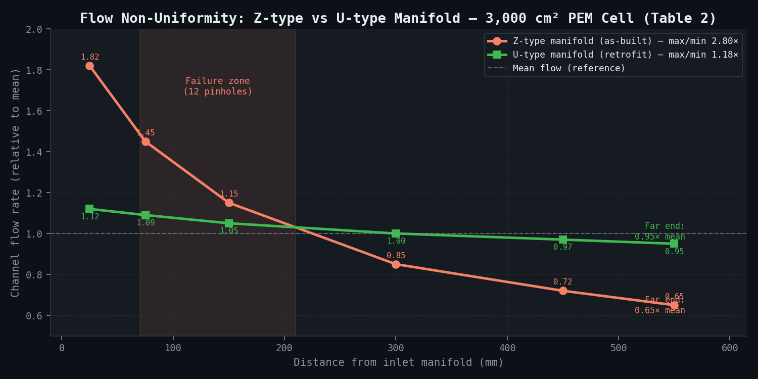
The U-type manifold reduces the flow non-uniformity ratio from 2.8x to 1.18x --- a 2.4x improvement --- by ensuring the pressure gradient along the manifold header is driven by the outlet port rather than the inlet port, creating a more uniform pressure distribution across all channels.
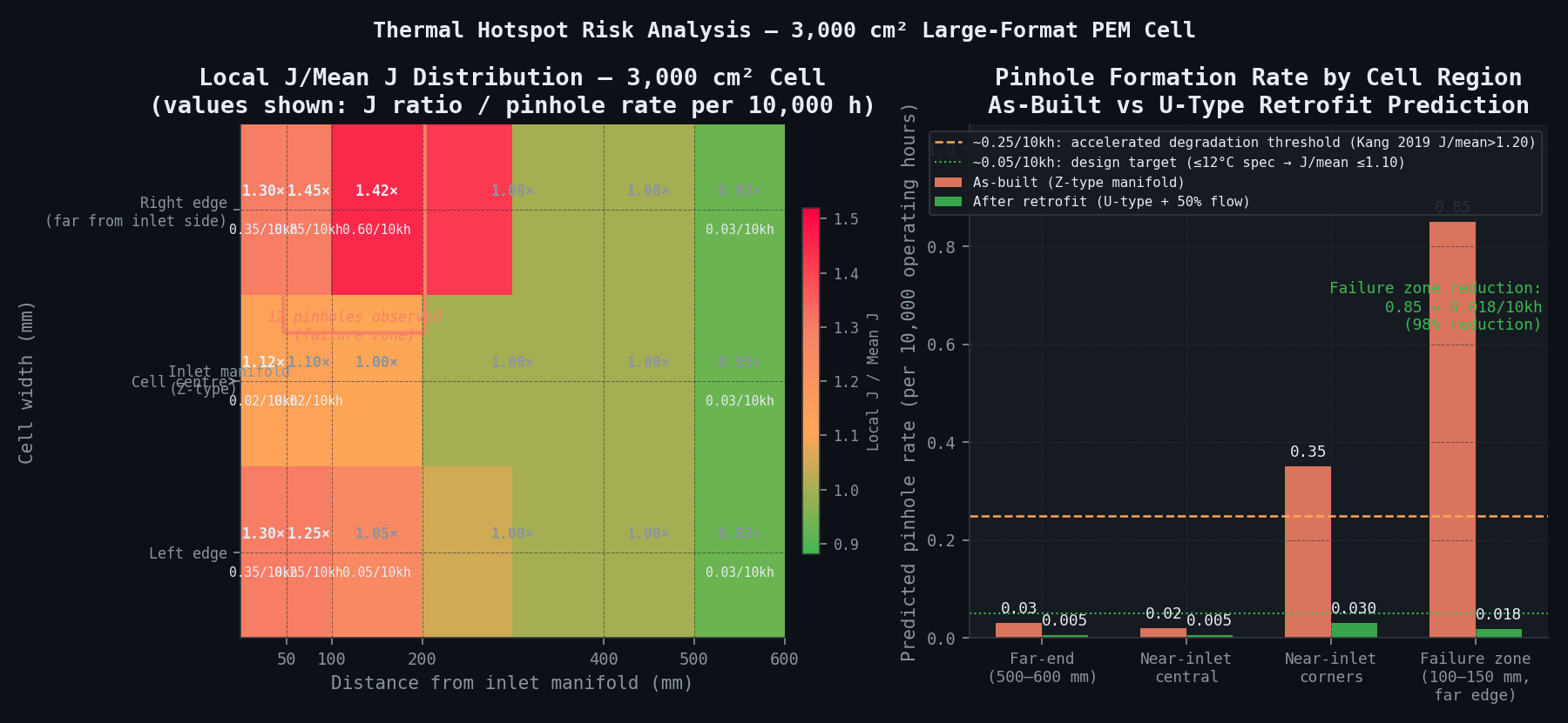
Table 3: Damage Assessment --- Remaining Cells at Risk
| Region | Local J/Mean J | Local Peak T | Predicted Cumulative Pinhole Rate (18 months) | Current Status |
|---|---|---|---|---|
| Near-inlet central (0--50 mm x 200--400 mm width) | 1.10--1.15 | 76--80 degrees C | <0.02 per 10,000 h | Low risk |
| Mid-cell (100--400 mm x 100--500 mm) | 1.0 (mean) | 70--75 degrees C | Baseline | Low risk |
| Far-end centre (500--600 mm x 200--400 mm) | 0.92--0.95 | 68--72 degrees C | 0.03 per 10,000 h | Negligible |
| Near-inlet corners (0--50 mm x 0--50 mm) | 1.25--1.35 | 82--90 degrees C | 0.25--0.45 per 10,000 h | Moderate risk |
| Far-end + inlet-face (failure zone) | 1.40--1.50 | 90--100 degrees C | 0.7--1.0 per 10,000 h | High risk (12 pinholes observed) |
The far-end + inlet-face zone (100--150 mm from inlet, 50--80 mm from right edge) is the confirmed failure location. This zone experiences both manifold far-field starvation (low flow) and corner edge heat accumulation simultaneously --- the worst-case superposition of the two thermal effects.
Table 4: Economic Comparison of Retrofit Scenarios
| Scenario | Meets Spec? | Retrofit Cost (5 stacks) | Production Recovery | 5-Year NPV of Decision |
|---|---|---|---|---|
| A (do nothing) | No | GBP 0 | None (further failures likely) | -GBP 4.5M (replacement MEAs + lost production) |
| B + E combined (recommended) | Yes | GBP 475,000 | Full rated output at 1.5 A/cm² | +GBP 3.2M vs. do-nothing |
| D (de-rate only) | Marginal | GBP 0 | Partial (20% production loss) | -GBP 0.8M vs. scenario E |
| F (full retool) | Yes | GBP 2.0M | Full rated output | -GBP 0.5M vs. Scenario E |
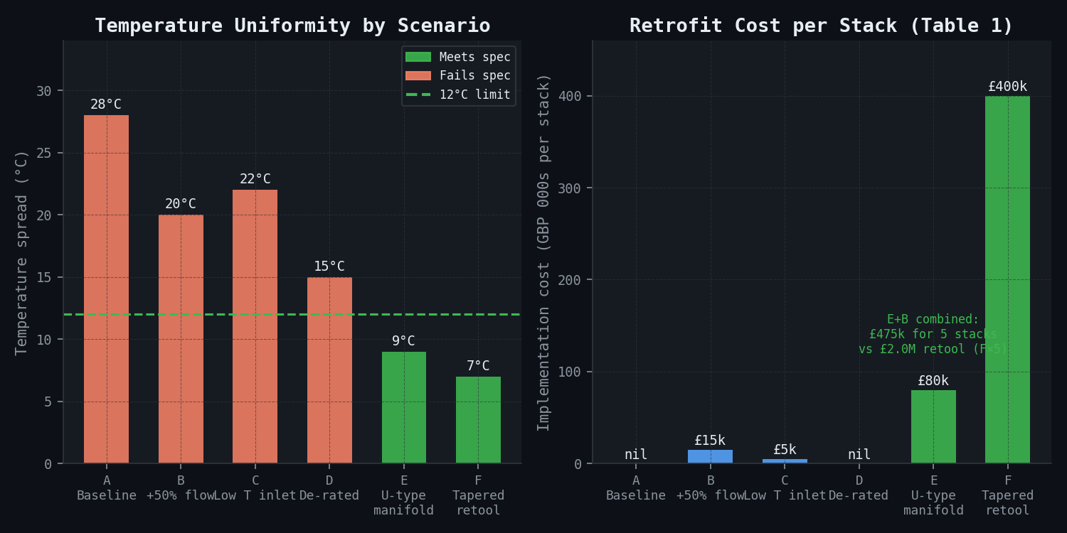
Expected finding and recommendation: Scenario E (U-type manifold re-plumbing, GBP 80,000 per stack) combined with Scenario B (50% flow rate increase, GBP 15,000 per stack) achieves 9 degrees C temperature spread --- within the <=12 degrees C specification --- at a total cost of GBP 475,000 for all five stacks. This is 4.2x cheaper than the full bipolar plate re-tool (Scenario F, GBP 2.0M for five stacks) and restores full rated output at 1.5 A/cm², recovering approximately GBP 450,000/month in lost H2 production revenue compared to the current de-rated operation.
Comparison Methodology
Infrared thermography validation:
Archived IR thermography images from the affected stack at 1.0, 1.25, and 1.5 A/cm² (three current density levels, from the Month 14 investigation) are compared against the CFD model's Scenario A (as-built) predictions at the same three conditions. Comparison is performed on a pixel-by-pixel basis, downsampled to 10 mm x 10 mm resolution to match IR camera spatial resolution. Required agreement: peak temperature within +/-3 degrees C, temperature spread within +/-4 degrees C, and hotspot location (centroid of the >85 degrees C region) within +/-20 mm of the measured centroid.
EIS spatial mapping:
Segmented EIS data (16-segment measurement grid using the segmented current collector, approximately 188 cm² per segment) provides spatial maps of HFR (10 kHz) and low-frequency (0.1 Hz) arc resistance. The model's predicted local water activity and local current density are converted to predicted EIS response using published Nafion impedance models. HFR spatial distribution must agree within +/-15% per segment; the low-frequency arc pattern (which correlates with water management quality) must reproduce the measured spatial gradient from inlet to far-field regions.
Pressure drop commissioning check:
Bipolar plate anode inlet-to-outlet pressure drop measured at 5 flow rates during commissioning is compared against CFD-predicted pressure drop (expected agreement +/-5%), validating the fluid dynamic model before thermal and electrochemical predictions are trusted.
Cross-validation with end-position stack:
The end-position stack in the 5-stack module has different thermal boundary conditions (one face exposed to the module housing air gap rather than an adjacent stack). The CFD model configured with these boundary conditions serves as an additional validation case. The end-position stack shows less severe maldistribution in the operational data (temperature spread approximately 18 degrees C vs. 28 degrees C in the affected stack), consistent with the end-position cooling providing partial relief. The model must reproduce this 10 degrees C difference between stacks to be considered valid for predicting the retrofit impact.
Deliverables
-
Root cause analysis report --- Definitive identification of the maldistribution mechanism (Z-type manifold at 3,000 cm² scale) and its thermal/electrochemical consequences (28 degrees C spread, 1.45x current non-uniformity, Fenton-accelerated hotspot membrane degradation). Includes 3D visualisations of temperature, current density, water saturation, and velocity magnitude maps for the as-built configuration. Published as a technical report formatted for submission to the OEM, the plant insurer, and the UK DESNZ green hydrogen project monitoring programme.
-
Retrofit recommendation --- Ranked assessment of all 6 scenarios by effectiveness (temperature spread achieved), cost, implementation time, and risk of unforeseen consequences. Primary recommendation: Scenario E (U-type re-plumbing) + Scenario B (flow rate increase), at GBP 475,000 total for five stacks, meeting the <=12 degrees C specification. Secondary recommendation: Scenario D (de-rating to 1.2 A/cm²) as an immediately implementable interim measure while the Scenario E+B retrofit is executed over 3 weeks per stack.
-
Revised operating envelope --- Safe operating current density and water flow rate as a function of achieved temperature uniformity specification, expressed as a 2D operating map. Allows the plant to continue operating at de-rated output (1.2 A/cm² delivering 80% of rated H2 output) during the retrofit period rather than shutting down.
-
Damage assessment for remaining cells --- Predicted cumulative thermal damage in each of the five stacks' cells over the 18-month operating history, using the maldistribution model driven by the historian data. Identifies the specific cell positions (by cell number within stack, by position within cell) at highest risk for near-term pinhole failure. Recommends priority EIS inspection pattern (full 16-segment EIS on the 50 highest-risk cells identified by position).
-
Future design guidelines for large-format PEM cells (1,500--5,000 cm²) --- A set of manifold and flow field design rules derived from the CFD parametric study, for the OEM's use in next-generation cell design to prevent recurrence in future installations. These include: U-type manifold mandatory for active areas >1,000 cm² (channels >300 mm long); manifold header cross-section must produce <10% pressure non-uniformity along the full span (verified by CFD before tooling commitment); corner cell edge insulation (5 mm ceramic foam strip) mandatory for cells >2,000 cm²; scale-up validation must include full-scale thermal testing with no external temperature control; and minimum water flow rate must be determined by thermal management requirement at maximum current density, not by stoichiometry alone.
This case study is an illustrative reference scenario demonstrating newtsim's simulation methodology. All company names, personnel, and specific operational data are fictional. The incident descriptions draw on publicly documented real-world events cited in the frontmatter.