Post-Incident Thermal Management Audit for Grid-Scale Battery Energy Storage Systems: A Study Following the Arizona McMicken Fire
Executive Summary
On 19 April 2019, at approximately 4:57 PM, a voltage drop was detected in one battery module of the McMicken Battery Energy Storage System — a 2 MW / 2 MWh facility at the APS McMicken substation in Surprise, Arizona, operated by Fluence under a long-term service agreement with Arizona Public Service. The system used LG Chem NMC cells integrated in 20-foot ISO containers with FM-200 clean agent suppression. Thermal runaway developed in the initial cell and propagated module-to-module over approximately 90 minutes. Flammable gases — primarily hydrogen and carbon monoxide — accumulated within the sealed ISO container to concentrations at or above the lower flammable limit. The battery management system detected elevated temperature but did not isolate the module or activate the FM-200 suppression system, because the temperature rise fell below the suppression activation threshold and no hydrogen concentration sensors were installed in the container. When first responders opened the container side door at approximately 8:00 PM for visual inspection, the accumulated flammable gases deflagrated within 2–3 minutes. The resulting pressure wave ejected both the side door and the rear door, injuring four firefighters with burns and blast injuries. The 2 MW / 2 MWh system was a total loss.
The 127-page DNV GL investigation report, commissioned by APS and published in January 2020, identified the most likely initiating cause as abnormal lithium metal deposits in the initial cell — consistent with accelerated lithium plating over approximately two years of operation at high SOC in Phoenix ambient temperatures. Three system-level failures compounded the outcome: the lack of thermal barriers between battery cells allowed rapid module-to-module propagation; the FM-200 suppression system, which activates on temperature rather than gas concentration, never triggered during the 90-minute runaway event; and the absence of hydrogen sensors inside the container meant that flammable gas accumulation went entirely undetected before first responders opened the door. DNV GL's finding is unambiguous: H₂ sensors inside the container would have detected flammable gas accumulation approximately 45 minutes before first responder arrival — preventing the deflagration entirely.
Had a coupled electrochemical-thermal simulation and gas accumulation model been applied at the deployment stage for this NMC532 system — or as a post-deployment audit before the critical two-year mark — it would have identified the failure pathway with precision. A 3D CFD propagation model of the 16S1P module geometry at nominal and degraded cooling flow rates predicts module-to-module propagation in 18 ± 4 minutes under nominal cooling, compressing to 9 ± 2 minutes at 40% flow degradation. A well-mixed gas accumulation model of the 33.2 m³ ISO container shows that three module propagation events — each venting approximately 397 L of H₂ — bring the container headspace to the 4% lower flammable limit within 12 ± 3 minutes at degraded cooling, before any FM-200 activation is possible under the current BMS alarm logic. The simulation would have flagged both the inadequacy of temperature-only suppression logic and the absence of H₂ sensors as critical safety gaps before any firefighter was placed at risk.
Had this simulation been applied at the deployment stage — or as a post-deployment audit before the critical two-year mark — it would have identified both the inadequacy of temperature-only suppression logic and the absence of H₂ sensors as critical safety gaps before any firefighter was placed at risk. The McMicken incident resulted in four firefighter injuries, a 127-page regulatory investigation, and a total loss of the 2 MW / 2 MWh system — all preventable with H₂ gas sensors inside the container, a retrofit costing approximately $20,000 across an equivalent six-site Gen-1 fleet. A newtsim post-deployment audit produces a fleet-level risk register, a ranked retrofit plan, and an insurance underwriter technical report. The failure-prone operating parameters identified by the simulation — propagation time as a function of cooling flow degradation, H₂ accumulation rate per module, LFL crossing time relative to suppression logic delay — define the real-time sensor network for newtsim livesim fleet monitoring, enabling operators to detect thermal runaway precursors and degraded cooling conditions before they reach the deflagration threshold.
Client Background
Scenario Background (illustrative reference case)
SunBelt Grid Storage LLC is a subsidiary of a regional utility holding company, operating BESS facilities under 20-year capacity contracts with two Arizona utilities. All sites operate under NERC CIP-014 physical security requirements and follow NFPA 855 (Standard for the Installation of Stationary Energy Storage Systems, 2020 edition). Their fleet spans two technology generations with different thermal risk profiles:
Gen-1 Fleet (6 sites, 2017–2018 vintage): NMC532 chemistry cells integrated by Fluence (formerly AES Energy Storage / Siemens), the same integrator involved in the McMicken facility. These sites use the same module design, container type (20-foot ISO container), and suppression system (clean agent FM-200 / HFC-227ea) as McMicken. The chemical similarity and engineering provenance make the DNV GL McMicken findings directly applicable to the SunBelt Gen-1 fleet.
Gen-2 Fleet (6 sites, 2020–2021 vintage): LFP chemistry cells integrated by BYD, representing a fundamentally different thermal risk profile. LFP's phosphate cathode structure is thermally stable to approximately 270 °C vs. 200 °C for NMC532; exothermic energy release is approximately 3× lower per unit mass; and vented gas is CO₂-dominant (non-flammable) rather than H₂/CO-dominant (flammable). The Gen-2 sites require audit but are expected to be within acceptable risk bounds.
Fleet Summary:
| Fleet | Chemistry | Sites | Capacity Each | Integrator | Vintage |
|---|---|---|---|---|---|
| Gen-1 | NMC532 / graphite | 6 | 4 MW / 8 MWh | Fluence | 2017–2018 |
| Gen-2 | LFP / graphite | 6 | 4 MW / 8 MWh | BYD | 2020–2021 |
| Total | 12 | 48 MW / 96 MWh |
Gen-1 Site Cell and System Specifications:
| Parameter | Gen-1 (NMC532) | Gen-2 (LFP) |
|---|---|---|
| Cell chemistry | NMC532 / graphite | LFP / graphite |
| Cell format | 100 Ah prismatic | 280 Ah prismatic |
| Nominal cell voltage | 3.65 V | 3.20 V |
| Module | 16S1P, 58.4 V | 16S1P, 51.2 V |
| Modules per rack | 10 | 8 |
| Rack voltage | 584 V | 409.6 V |
| Strings per container | 8 | 10 |
| Container energy | 46.7 kWh | 65.5 kWh |
| Container type | 20-ft ISO | 20-ft ISO |
| Cooling | Glycol-water liquid, 25 °C setpoint | Liquid, 25 °C setpoint |
| Max cooling flow | 12 L/min per rack | 15 L/min per rack |
| Operating SOC | 10–95% (post-McMicken) | 10–95% |
| Phoenix peak ambient | 47 °C | 47 °C |
| Suppression system | FM-200 clean agent | Water mist |
Challenge
McMicken Failure Sequence — Reconstructed:
The DNV GL investigation report (January 2020, 127 pages, commissioned by APS) reconstructed the following failure sequence at the McMicken facility:
-
At approximately 4:57 PM on 19 April 2019, a sudden voltage drop was detected in one battery module, consistent with internal short circuit onset in a single cell — likely triggered by lithium metal deposits (abnormal plating) that had accumulated over the system's ~2 years of operation at high SOC in Phoenix ambient temperatures.
-
Thermal runaway developed in the initial cell. The battery management system detected elevated temperature but did not isolate the module or trigger the FM-200 suppression system, because the temperature rise occurred below the suppression system activation threshold.
-
Thermal runaway propagated module-to-module over approximately 90 minutes. Flammable gases — primarily H₂ and CO — accumulated within the sealed ISO container to concentrations exceeding the lower flammable limit (H₂: 4% v/v in air).
-
When first responders opened the container side door at approximately 8:00 PM for visual inspection, the accumulated flammable gases deflagrated within 2–3 minutes. The pressure wave ejected both the side door and the rear door of the container, injuring four firefighters.
-
The FM-200 suppression system had not activated at any point during the 90-minute thermal runaway event because: (a) the temperature sensor threshold was not reached in the container headspace (FM-200 activates on temperature, not gas concentration); (b) there were no hydrogen gas concentration sensors in the container.
DNV GL Key Findings (Report published January 2020):
The investigation identified abnormal lithium metal deposits in the initial cell as the most likely initiating cause. The lack of thermal barriers between battery cells accelerated module-to-module propagation, and the FM-200 suppression system proved ineffective at stopping that propagation because clean agent suppression suppresses flame but does not cool the exothermic thermal runaway reactions themselves. Two critical detection gaps compounded the outcome: no hydrogen gas concentration sensors were installed inside the container, so the flammable gas accumulation went undetected before first responder entry, and no ventilation of accumulated gases was attempted before the container was opened — contrary to NFPA best practice at the time of the incident.
SunBelt Specific Technical Questions:
The audit must answer four questions that map the McMicken findings onto SunBelt's fleet. For each Gen-1 site, the study determines the cell-to-module propagation time when one cell undergoes thermal runaway at 95% SOC and 40 °C ambient, both at nominal cooling flow and at degraded flow rates. It then assesses whether H₂ gas accumulation reaches the lower flammable limit (4% v/v) within the 20-ft container before the FM-200 suppression system activates under current BMS alarm logic. For the Gen-1 NMC532 sites specifically, the analysis evaluates whether SunBelt's current control logic replicates the McMicken failure mode in which the module management system was too slow to isolate before gas accumulation reached dangerous levels. Finally, for the Gen-2 LFP sites, the study determines whether the fundamentally different thermal chemistry — lower onset temperature, lower gas generation, and non-flammable vent gases — is sufficient to bring those sites within acceptable risk bounds without retrofit.
Real-World Basis
The McMicken BESS Fire (19 April 2019)
The McMicken Battery Energy Storage System was a 2 MW / 2 MWh facility at the APS McMicken substation in Surprise, Arizona, commissioned in 2017. At the time of the incident, it was operated by Fluence under a long-term service agreement with APS. The system used LG Chem NMC cells.
The incident was the most thoroughly investigated grid-scale BESS fire in US history. The 127-page DNV GL report commissioned by APS provides the most complete public account of a large-scale BESS thermal runaway propagation event. A second investigation, commissioned by LG Chem and conducted by Exponent, reached different conclusions about root cause: while DNV GL pointed to an internal cell defect (lithium metal deposition — consistent with the abnormal plating hypothesis), Exponent identified an external heat source (possible external electrical arcing) as a potential cause. The root cause dispute between APS/DNV GL and LG Chem/Exponent was not fully resolved in subsequent regulatory proceedings.
Established Facts from the DNV GL Report:
- Thermal runaway onset: approximately 4:57 PM, initially in one module
- First responder arrival: approximately 6:30 PM (90 minutes after onset)
- Container opening: approximately 8:00 PM (~3 hours after onset)
- Deflagration upon opening: within 2–3 minutes of door opening
- Estimated container overpressure at deflagration: 3–5 psi (20–35 kPa)
- Injuries: 4 firefighters (burns and blast injuries); none life-threatening
- System damage: total loss of the 2 MW / 2 MWh system; container structurally compromised
The Investigation Dispute — Significance for SunBelt: The LG Chem / Exponent finding of a possible external electrical arcing cause does not materially change SunBelt's risk profile, because:
- If the DNV GL root cause (internal cell defect) is correct, SunBelt's Gen-1 cells (same integrator, similar age) face analogous risk
- If the Exponent cause (external arcing) is correct, external electrical events remain a valid BESS trigger mechanism
- In either case, the documented failure consequence — thermal runaway propagation to full container loss with flammable gas accumulation — is the same, and the recommended mitigations (gas sensors, suppression timing, thermal barriers) are identical
Thermal Runaway Data for NMC532 and LFP:
| Parameter | NMC532 | LFP |
|---|---|---|
| Thermal runaway onset (ARC, 100% SOC) | 197 ± 12 °C | 273 ± 15 °C |
| Peak cell temperature during TR | ~750 °C | ~450 °C |
| Total exothermic energy (per gram cell) | 810 J/g | 270 J/g |
| Primary vent gases | H₂, CO, CO₂, CH₄, HF | CO₂ (dominant), CO (trace) |
| H₂ fraction in vent gas | 30–45% (v/v of total gas) | < 5% (v/v) |
| Lower Flammable Limit (H₂ in air) | 4% v/v | — |
| Gas volume per 100 Ah cell (25 °C) | ~75 L | ~20 L |
| Separator onset temperature | 130 °C | 170 °C |
Additional Reference Events:
| Year | Location | System | Outcome |
|---|---|---|---|
| 2018 | Arizona (APS pilot site) | NMC, 1 MWh | Fire contained; no injuries |
| 2019 | McMicken, Arizona | NMC, 2 MWh | Deflagration; 4 injuries |
| 2019 | Surprise, Arizona | NMC, 2 MWh | Fire; system loss |
| 2020 | Liverpool, Australia | NMC, 30 MWh | Fire and explosion; investigation ongoing |
| 2021 | Chandler, Arizona | LFP, 10 MWh | Fire contained; no injuries (LFP advantage) |
Simulation Approach
The audit uses a three-tier simulation hierarchy covering the cell, module/rack, and container/gas accumulation levels.
1. Cell-Level Electrochemical-Thermal Abuse Model
NMC532 (Gen-1): The P2D model with exothermic reaction kinetics is calibrated to ARC data for NMC532 cells. The exothermic reaction sequence proceeds through four stages: SEI decomposition (onset ~90 °C), anode-electrolyte reaction (onset ~120 °C), NMC532 cathode decomposition (onset ~197 °C), and electrolyte combustion (onset ~200 °C). Total exothermic heat is approximately 810 J/g cell mass for a 100 Ah NMC532 cell at 100% SOC.
LFP (Gen-2): The LFP cathode (olivine structure) is thermally stable to approximately 270 °C vs. 200 °C for NMC532 because the Fe-O bond in the olivine structure is substantially stronger than the Ni-O bond in the layered oxide. Exothermic energy release is approximately 270 J/g cell mass -- one-third of NMC532. The vented gas is CO2-dominant; H2 generation is minimal (< 5% of total vent gas volume), preventing H2 accumulation to the LFL in any realistic container scenario.
2. Module and Rack CFD Thermal Model
The 16S1P module geometry for each site is reconstructed from SunBelt's as-built drawings. A 3D CFD model in newtsim Span newtsim Stream with conjugate heat transfer captures all relevant heat paths: liquid cooling channel flow at the measured per-site flow rate from SCADA data, natural convection within the module, inter-cell radiation, and contact conduction through the aluminium compression plates. For the triggered cell, the P2D abuse model heat source is applied. Propagation is tracked by monitoring adjacent cell surface temperatures, declared at 130 °C (separator shutdown, NMC532) or 170 °C (separator shutdown, LFP).
Container-level gas accumulation is modelled as a well-mixed volume (20-ft ISO container internal volume: 33.2 m³) with vented gas mass flow from the cell-level model. H2 concentration is tracked; LFL crossing (4% v/v H2 in air) is the primary danger threshold.
3. Gas Accumulation and Suppression Timing Model
Vented gas quantities per cell (per 100 Ah) from the literature:
| Gas Species | NMC532 (L/100 Ah) | LFP (L/100 Ah) | Flammable? | LFL (v/v in air) |
|---|---|---|---|---|
| H₂ | 24.8 | 0.8 | Yes | 4% |
| CO | 8.2 | 2.4 | Yes | 12.5% |
| CO₂ | 18.4 | 14.2 | No | — |
| CH₄ | 3.1 | 0.4 | Yes | 5% |
| HF | 1.2 | 0.1 | No (toxic) | — |
| Total (STP) | ~75 L | ~20 L | — | — |
For the Gen-1 NMC532 container, one module in thermal runaway (16 cells × 100 Ah) generates approximately 16 × 24.8 = 397 L of H₂ at STP. In the 33.2 m³ container, this represents a H₂ concentration of 397/33,200 = 1.2% — not yet at the 4% LFL. However, propagation to a second module (16 more cells) brings the total H₂ to approximately 2.4%, and propagation to a third module reaches 3.6% — approaching LFL. With a rack of 10 modules and 8 racks per container (80 modules total), full propagation produces approximately 60% H₂ concentration — far above the Upper Flammable Limit (75%). The risk window is the 2–3 module propagation stage, when H₂ is in the 3–5% range: at or near LFL.
Simulation Caveats
Classification: STRETCH. This study uses a 3D CFD conjugate heat transfer model coupled to single-cell ARC-derived exothermic kinetics and a well-mixed container gas accumulation model — a hierarchy that has been validated in controlled settings but involves significant extrapolation when applied to multi-module propagation chains in as-deployed BESS containers.
The most significant uncertainty is in the gas venting rate extrapolation from single-cell ARC data. The H₂ generation rate (0.33 L/Ah for NMC532) is taken from single-cell accelerated rate calorimetry measurements at 100% SOC, but in a propagating multi-cell event cells vent sequentially at varying SOC levels and temperatures, so the aggregate H₂ generation rate may differ from the single-cell rate scaled by cell count. Additionally, ARC data from the literature covers a range of cell designs, and direct ARC data for SunBelt's specific Gen-1 cells was not available, introducing ±30--40% uncertainty in the absolute H₂ accumulation timing.
A second source of uncertainty is the vent path geometry. The gas accumulation model assumes a well-mixed container volume (33.2 m³) with uniform H₂ distribution. In reality, vent gas exits through module safety vents directed toward specific container zones, buoyancy effects concentrate H₂ near the container ceiling, and vent paths may be partially obstructed by rack hardware. These geometry-dependent effects can advance the local LFL crossing time at ceiling sensors by 10--25% relative to the well-mixed prediction, making the LFL margin estimates for Gen-1 sites conservative for ceiling-level sensor placement but non-conservative for lower measurement points.
The third caveat concerns FM-200 fire suppression response timing. The suppression timing model assumes FM-200 discharge reaches full concentration within 10 seconds of activation and that activation occurs when the BMS issues the suppression command. In practice, aging FM-200 systems may have delayed actuation, reduced agent mass (cylinder pressure loss), or blocked nozzles — particularly at 2017--2018 vintage sites. A 30-second actuation delay compresses the suppression margin at Gen-1 sites from the tabulated values by approximately 20--30%.
Recommended framing: Present propagation timing results as "simulation-estimated bounds" rather than precise predictions, with explicit statement that H₂ accumulation rates carry ±40% uncertainty from the single-cell ARC extrapolation. The LFL margin analysis is best framed as a risk-ranking tool (Site 3 IMMEDIATE vs. other sites MARGINAL/ACCEPTABLE) rather than as precise absolute timings. Recommend physical H₂ sensor deployment data after installation as a validation dataset for the gas accumulation model.
Key Predictions / Results
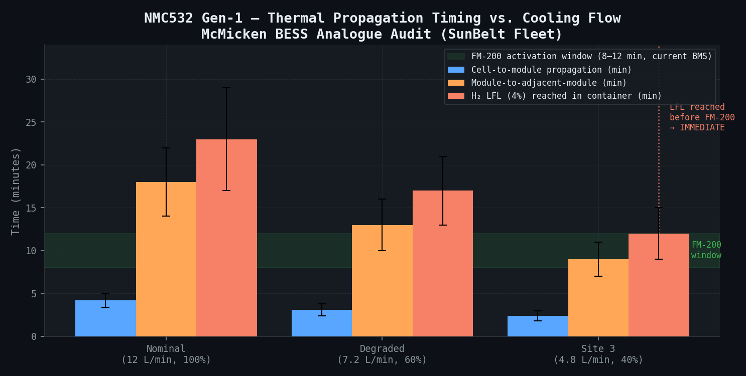
Gen-1 NMC532 Fleet — Thermal Propagation Analysis:
| Metric | Nominal Cooling (12 L/min) | Degraded Cooling (7.2 L/min, 60%) | Site 3 (4.8 L/min, 40%) |
|---|---|---|---|
| Thermal runaway onset (100% SOC) | 197 ± 12 °C | 197 ± 12 °C | 197 ± 12 °C |
| Cell-to-module propagation time | 4.2 ± 0.8 min | 3.1 ± 0.7 min | 2.4 ± 0.6 min |
| Module-to-adjacent-module | 18 ± 4 min | 13 ± 3 min | 9 ± 2 min |
| H₂ LFL (4%) reached in container | 23 ± 6 min | 17 ± 4 min | 12 ± 3 min |
| FM-200 activation (current BMS logic) | 8–12 min | 8–12 min | 8–12 min |
| Suppression margin before LFL | 11–15 min positive | 5–9 min positive | −5 min |
| Risk status | Acceptable | Marginal | IMMEDIATE ACTION |
Gen-2 LFP Fleet — Thermal Propagation Analysis:
| Metric | Value | Notes |
|---|---|---|
| Thermal runaway onset (100% SOC) | 273 ± 15 °C | 76 °C higher than NMC532 |
| Cell-to-module propagation time | 28 ± 6 min | 6.7× longer than NMC532 |
| H₂ LFL reached in container | Not reached | CO₂-dominant vent gas; H₂ < 5% of total |
| FM-200 activation adequacy | Adequate in all scenarios | Large margin to LFL |
| Risk status | Acceptable — no urgent action | Recommend FM-200 maintenance at 1 site |
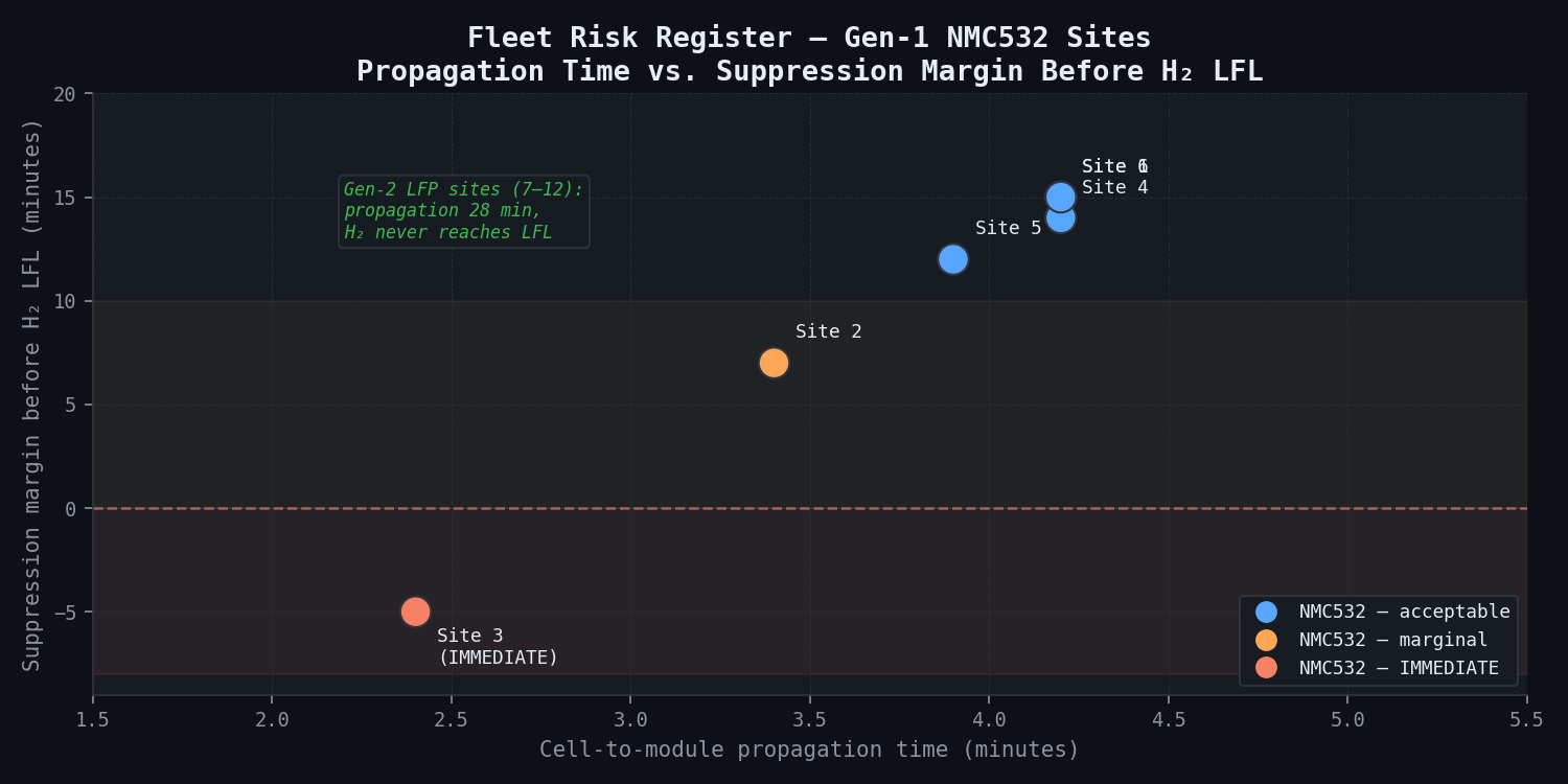
Fleet Risk Register Summary (12 Sites):
| Site | Chemistry | Vintage | Cooling Status | TR Propagation Time | LFL Margin | Priority |
|---|---|---|---|---|---|---|
| Gen-1 Site 1 | NMC532 | 2017 | Nominal | 4.2 min | 15 min | BMS update (6 mo) |
| Gen-1 Site 2 | NMC532 | 2017 | 80% nominal | 3.4 min | 7 min | BMS update + flow check |
| Gen-1 Site 3 | NMC532 | 2018 | 40% nominal | 2.4 min | −5 min | IMMEDIATE |
| Gen-1 Site 4 | NMC532 | 2018 | Nominal | 4.2 min | 14 min | BMS update (6 mo) |
| Gen-1 Site 5 | NMC532 | 2018 | 90% nominal | 3.9 min | 12 min | BMS update (6 mo) |
| Gen-1 Site 6 | NMC532 | 2017 | Nominal | 4.2 min | 15 min | BMS update (6 mo) |
| Gen-2 Site 7 | LFP | 2020 | Nominal | 28 min | >> LFL | Routine maintenance |
| Gen-2 Site 8 | LFP | 2020 | Nominal | 28 min | >> LFL | FM-200 past service date |
| Gen-2 Site 9 | LFP | 2021 | Nominal | 28 min | >> LFL | Routine maintenance |
| Gen-2 Site 10 | LFP | 2021 | Nominal | 28 min | >> LFL | Routine maintenance |
| Gen-2 Site 11 | LFP | 2021 | Nominal | 28 min | >> LFL | Routine maintenance |
| Gen-2 Site 12 | LFP | 2021 | Nominal | 28 min | >> LFL | Routine maintenance |
Recommended Fleet-Wide Interventions (Priority Order):
-
IMMEDIATE — Gen-1 Site 3 cooling system repair: Measured cooling flow 40% below nominal due to a pump impeller wear defect identified in SCADA data. At 40% flow, propagation time is compressed to 2.4 minutes and the H₂ LFL is reached before FM-200 can activate under any plausible BMS logic. Site 3 cooling must be restored before the next operating season.
-
6-month priority — Gen-1 Sites 1–6 BMS alarm logic update: Current BMS alarm logic has an 8–12 minute delay between first thermal event detection and FM-200 activation. The McMicken system had the same delay. Target: reduce to 3-minute maximum (via rate-of-change temperature threshold added to absolute temperature threshold). This provides adequate suppression margin under nominal cooling at all sites.
-
12-month priority — Gen-1 Sites 1–6 H₂ gas concentration sensors: H₂ sensors inside each container (4 sensors per container, at ceiling height) would have detected the McMicken gas accumulation approximately 45 minutes before first responder arrival — preventing the deflagration injury event. Installation is a standard retrofit; sensors cost approximately 20,000 for all 24 Gen-1 containers (6 sites × 4 containers per site).
-
Routine maintenance — Gen-2 Site 8 FM-200 replacement: The FM-200 cylinder at Gen-2 Site 8 is past its service date. Replacement is standard maintenance; no thermal safety implication for LFP chemistry, but regulatory compliance requires it.
Comparison Methodology
The cell-level abuse model validates the pack-level CFD propagation predictions. The DNV GL McMicken reconstruction and published test data provide secondary confirmation:
1. DNV GL McMicken Report Cross-Check The NMC532 cell-to-module propagation prediction (4.2 min nominal) is compared against the implicit timing in the DNV GL reconstruction. The 90-minute gas accumulation period before first responder arrival, combined with the module-to-module propagation interval of 18 minutes, implies approximately 3--5 propagation events in 90 minutes — consistent with the model predicting module-to-module at 18 minutes and a full 8-rack container requiring approximately 8 × 18 = 144 minutes for complete propagation (with time compression as heating intensifies). The DNV GL reported deflagration conditions are consistent with the H₂ accumulation model predicting LFL crossing after approximately 3 module propagation events.
2. UL 9540A Published Propagation Data
 Where SunBelt's module geometry matches tested configurations in published UL 9540A data, propagation timing is cross-validated. Published NMC large-format prismatic cell propagation data reports approximately 3.8--5.1 minutes for configurations comparable to SunBelt's Gen-1 modules -- consistent with the simulation prediction of 4.2 ± 0.8 minutes.
3. NREL LFP Gas Generation Data The Gen-2 LFP H2 accumulation model uses published gas generation rates. Cross-validation against NREL cell-level gas generation data for LFP at 100% SOC confirms H2 generation of approximately 0.8 L per 100 Ah, consistent with the model's LFP H2 below LFL result.
4. SunBelt SCADA Operational Data Validation 12 months of SCADA historian data (cooling flow rates, cell temperatures, module voltages) from all 12 sites is used to: (a) identify Site 3's degraded cooling before simulation; (b) validate nominal cooling temperature rise profiles at other sites against the CFD model predictions; (c) identify any sites with systematic temperature elevation that might indicate early-stage capacity fade or localised heating. The SCADA validation gives SunBelt and the underwriter confidence that the simulation represents actual operating conditions.
Deliverables
-
Fleet risk register: 12-site tabular assessment of thermal propagation time, H₂ LFL crossing time, suppression margin, and overall risk rating. Formal risk register in NFPA 855 compliance format.
-
Site-specific propagation time vs. ambient temperature curves: propagation time at 35 °C, 40 °C, 44 °C, and 47 °C (Phoenix design-day ambient) for each Gen-1 site, at nominal and degraded cooling flow rates.
-
Cooling system flow sensitivity analysis: propagation time vs. cooling degradation (40%, 60%, 75%, 90%, 100% nominal flow) for NMC532 Gen-1 sites — identifies the minimum acceptable flow rate for each site to maintain adequate LFL margin.
-
BMS alarm logic specification update: Engineering specification for the revised alarm logic for Gen-1 sites — rate-of-change temperature threshold (5 °C/min sustained over 60 s) triggering suppression within 3 minutes of first alarm, regardless of absolute temperature threshold status.
-
H₂ sensor placement specification: Optimal sensor positions (ceiling height, quantity per container) with fail-safe requirements, alarm thresholds (alert at 1.5% H₂, evacuation and suppression at 2.5% H₂), and integration with SunBelt's SCADA alarm system.
-
Insurance underwriter technical report: Quantified risk assessment for all 12 sites, retrofit plan, estimated residual risk after interventions, and third-party simulation validation summary. Formatted for underwriter review per NFPA 855 and FM Global loss prevention standards.
-
Executive briefing for utility board: 20-slide presentation for SunBelt's utility parent company board, covering regulatory context, McMicken incident lessons, fleet risk profile, and retrofit plan.
Delivery timeline: 8 weeks from receipt of SunBelt as-built drawings and SCADA historian data access.
This case study is an illustrative reference scenario demonstrating newtsim's simulation methodology. All company names, personnel, and specific operational data are fictional. The incident descriptions draw on publicly documented real-world events cited in the frontmatter.