Thermal Runaway Propagation Modelling for Lithium-Ion Battery Packs: Lessons from the Boeing 787 Dreamliner Incidents
Executive Summary
On 7 January 2013, a Japan Airlines Boeing 787-8 that had deplaned at Boston Logan International Airport approximately 75 minutes earlier was found smoking in the forward equipment bay. The APU battery — a GS Yuasa LVP65 8-cell lithium cobalt oxide module — had experienced an internal short circuit in cell 6, triggering thermal runaway that propagated to adjacent cells within 60–90 seconds. Nine days later, on 16 January 2013, an All Nippon Airways 787-8 on flight NH692 made an emergency landing at Takamatsu Airport after cockpit smoke and a main battery fault forced the crew to divert. The FAA issued Emergency Airworthiness Directive 2013-02-51 that same day, grounding every US-registered 787. By the end of the week, the entire global fleet of approximately 50 aircraft — operated by JAL, ANA, Air India, LOT Polish, Ethiopian, Qatar, and United — was grounded for 104 days, the longest commercial aircraft type grounding since the DC-10 in 1979.
The NTSB investigation (NTSB/AIR-14/01, December 2014) identified the root cause as an internal short circuit most likely initiated by a manufacturing defect — foreign object debris or electrode winding wrinkles in GS Yuasa's manual winding process — that created a separator weakness and triggered thermal runaway. Critically, Boeing's System Safety Assessment had "considered but ruled out" cell-to-cell propagation without providing quantitative analysis or justification. The SSA underestimated thermal runaway probability from manufacturing defects by at least two orders of magnitude. The financial consequences were severe: Boeing incurred approximately 200M in engineering and re-certification costs; GS Yuasa's share price fell 20% in the week following the Boston incident; total programme disruption across all operators exceeded $1.2B.
Had a coupled thermal/electrochemical simulation been applied at the cell design and pack design stage, it would have identified the critical vulnerability directly: that cell-to-cell propagation in the uninsulated GS Yuasa configuration occurs within 60–90 seconds of thermal runaway onset — less than one-sixth of the 360-second crew intervention window mandated by DO-311A Section 4.3.4. The simulation would have further shown that the thinner separators and higher electrode loadings characteristic of the next-generation high-energy LCO design concentrate lithium-ion flux at the separator face by approximately 35%, materially increasing the probability of a manufacturing-defect-induced ISC relative to the original design. No physical propagation test was run during 787 battery certification because the SSA did not flag propagation as a credible scenario — a gap that simulation would have closed before a single aircraft was delivered.
Had this simulation been run during cell qualification, it would have delivered what Boeing's SSA did not: a quantitative propagation delay versus insulation design curve, a regulatory compliance assessment against DO-311A Section 4.3.4, and a specific pack redesign specification (3–4 mm Pyrogel XT-E aerogel inter-cell blanket, 28 mm² vent channel) extending the predicted containment window from 110–140 seconds (non-compliant) to 420–480 seconds at 25 °C ambient. The Boeing 787 grounding lasted 104 days, costing Boeing approximately 1.2B in total programme disruption across all operators. A newtsim simulation would have identified the cell-to-cell propagation vulnerability before a single aircraft was delivered. Critically, the failure-prone cell parameters identified by the simulation — thermal runaway onset temperature, propagation delay as a function of SOC and ambient temperature, and the separator shutdown threshold — define the sensor network for newtsim livesim fleet monitoring, enabling real-time detection of thermal runaway precursors across an in-service aircraft fleet before they cascade.
Client Background
Scenario Background (illustrative reference case)
AeroCellix Systems is a Tier-1 aerospace battery supplier with approximately 340 engineers across facilities in Toulouse and Nagoya. The company holds qualification programmes with two major commercial airframe OEMs and has an active development contract for a 28 VDC APU battery system targeting entry-into-service in 2028 under the AX-400 programme designation.
The supplier's internal simulation capability is centred on newtsim Span newtsim Stream for structural and fluid thermal work, but the organisation has no in-house electrochemical modelling capability and no prior experience with abuse-condition simulation at the cell level. The gap between pack-level thermal FEM competence and cell-level electrochemical-thermal abuse modelling defines the scope of the study.
The cell chemistry selected for AX-400 is lithium cobalt oxide (LCO) cathode with graphite anode — consistent with the GS Yuasa cells implicated in the 2013 incidents — but at a higher energy density of 265 Wh/kg. This increase is achieved through thinner separators (16 µm trilayer PE/PP/PE versus the original 25 µm), higher electrode loading, and a reduced N/P ratio of 1.05. The thinner separator and tighter N/P ratio both increase sensitivity to manufacturing variability, directly analogous to the design trajectory that contributed to the GS Yuasa failure modes identified by the NTSB.
AX-400 Cell and Pack Specifications:
| Parameter | Value |
|---|---|
| Cell chemistry | LCO (LiCoO₂) / graphite |
| Cell format | Prismatic pouch, 50 Ah |
| Cell energy density | 265 Wh/kg |
| Cell dimensions | 148 × 91 × 9.5 mm |
| Pack configuration | 8S2P (16 cells total) |
| Pack nominal voltage | 201.6 V |
| Pack usable capacity | 100 Ah |
| Separator | 16 µm trilayer PE/PP/PE |
| Separator shutdown temperature | ~130 °C |
| Separator melt temperature | ~165 °C |
| Electrolyte | 1.2 M LiPF6 in EC:EMC:DMC (3:4:3 v/v) |
| Anode loading | 4.2 mAh/cm² |
| Cathode loading | 4.0 mAh/cm² |
| N/P ratio | 1.05 |
| Operating C-rates | 0.5C continuous discharge, 2C peak (30 s), 0.3C charge |
| Operating temperature range | −20 °C to +55 °C |
| Storage temperature | −40 °C |
| Target cycle life | 1,000 cycles to 80% capacity retention |
| Regulatory framework | EASA CS-25, FAA DO-311A |
Challenge
AeroCellix must demonstrate to regulators that a single-cell thermal runaway event within their 8S2P pack geometry will not propagate to adjacent cells within the DO-311A minimum crew-intervention window. The abuse trigger modelled is an ISC introduced by either: (a) a manufacturing-induced metallic particle bridging the separator gap in the electrode winding — consistent with the electrode winding wrinkle defects at GS Yuasa identified by the NTSB — or (b) dendritic lithium growth at the graphite anode following low-temperature charging below 0 °C.
The core engineering uncertainty is the cell-to-cell propagation window: the time elapsed between first-cell thermal runaway onset (electrolyte venting at approximately 148–152 °C cell surface temperature) and second-cell runaway trigger. The design question is whether the existing inter-cell insulation and vent channel architecture is sufficient to extend this window beyond 360 seconds.
Several technical sub-challenges interact to govern the propagation window.
The 16 µm separator — 36% thinner than the GS Yuasa original — reduces the mechanical barrier to dendrite penetration. At −10 °C charging conditions the anode potential approaches 0 V vs. Li/Li+ at the separator face within 4--5 minutes of 0.3C charging if the SEI is immature or damaged, creating lithium plating conditions across a wide electrode area rather than a single pinhole. Because the plating area scales with the ratio of separator thickness to lithium-ion diffusion path length, the thinner separator concentrates flux by approximately 35% at the separator face, materially increasing the probability of an ISC trigger relative to the original GS Yuasa design.
Vent pressure dynamics compound the thermal risk. During thermal runaway, electrolyte vapour — primarily EC/EMC decomposition products decomposing rapidly above 150 °C — vents from the triggered cell into the inter-cell space. The existing 12 mm² vent channel produces a computed 2.8 bar pressure pulse within 8 seconds of runaway onset, sufficient to mechanically compress adjacent cell casings by an estimated 0.3 mm, reducing the inter-cell gap and increasing conductive heat transfer by approximately 15%. At 80 kPa stack compression pressure the inter-cell contact conductance through the aluminium heat spreader and silicone pad reaches approximately 1,820 W/m²K — high enough that a triggered cell surface at 300 °C can drive adjacent-cell surface temperature to the 130 °C separator shutdown threshold within 90--150 seconds if no aerogel barrier is present.
The altitude cabin environment introduces an additional variable: at cruising altitude (0.75 atm) the boiling point of EC/EMC components drops by approximately 12--15 °C, meaning electrolyte vapour evolution begins earlier in the thermal runaway cascade. Cabin forced convection at approximately 2 m/s yields a convective heat transfer coefficient of approximately 22 W/m²K on exposed battery surfaces, a boundary condition that the FEM must capture accurately to produce credible propagation timing estimates.
Real-World Basis
The 2013 Boeing 787 Battery Incidents
The Boeing 787 Dreamliner experienced two battery incidents within nine days in January 2013, triggering the first grounding of a commercial aircraft type since the DC-10 in 1979.
Boston Logan Airport Incident (7 January 2013): A Japan Airlines 787-8 (registration JA829J) had deplaned at Gate B17 at Boston Logan International Airport approximately 75 minutes earlier when ground crew detected smoke in the forward equipment bay. The APU battery — a GS Yuasa LVP65 8-cell module at 29.6 V nominal — experienced an internal short circuit in cell 6 of 8, leading to thermal runaway that propagated to at least one adjacent cell. Electrolyte leaked from the battery enclosure and ignited on the hangar floor. Battery management unit thermocouple data recorded a maximum temperature of 260 °C — consistent with the LCO cathode decomposition exotherm onset at approximately 230 °C.
Takamatsu Emergency Landing (16 January 2013): An All Nippon Airways 787-8 (registration JA804A) on flight NH692 from Yamaguchi-Ube to Tokyo detected a low-capacity warning followed by a burning smell and main battery fault indication approximately 35 minutes after departure. Smoke was visible in the cockpit. The aircraft made an emergency landing at Takamatsu Airport. Post-incident inspection revealed thermal runaway in cell 8 of the 8-cell main battery module.
Fleet Grounding: The FAA issued Emergency Airworthiness Directive 2013-02-51 on 16 January 2013, grounding all 50 US-registered Boeing 787s. The global fleet of approximately 50 aircraft across JAL, ANA, Air India, LOT Polish, Ethiopian Airlines, Qatar Airways, and United was subsequently grounded. The grounding lasted until 27 April 2013 — 104 days.
NTSB Investigation Findings (NTSB/AIR-14/01, December 2014):
The NTSB investigation of the Boston Logan incident (docket DCA13IA037) produced a 44-page report and eight safety recommendations directed at Boeing, GS Yuasa, and the FAA. Key technical findings:
-
Root cause: Internal short circuit within cell 6 of the APU battery, exact origin undetermined but most likely initiated by a manufacturing defect — foreign object debris or electrode winding wrinkle — creating a separator weakness.
-
GS Yuasa manufacturing deficiencies: The manual electrode winding and hand-flattening process created wrinkles in the electrode foil at a detectable rate. The NTSB Airworthiness Factual Addendum found that: (a) the electrolyte filling process was inconsistent with industry practice, potentially producing incomplete SEI formation; (b) post-assembly battery inspections "could not reliably detect manufacturing defects caused by foreign object debris generated during manufacturing"; (c) GS Yuasa did not test the battery under the most severe conditions possible in service.
-
Boeing safety assessment failure: Boeing's System Safety Assessment had "considered but ruled out" cell-to-cell propagation of thermal runaway without providing analysis or justification — a fundamental gap that the NTSB flagged as the primary systemic failure. The SSA underestimated thermal runaway probability from manufacturing defects by at least two orders of magnitude.
-
Propagation timing: Reconstructed from battery management unit data, the initial cell failure occurred approximately 4–5 minutes before smoke detection. Propagation from cell 6 to adjacent cells occurred within 60–90 seconds of full thermal runaway onset.
-
Regulatory remediation: Boeing's approved fix was a stainless-steel over-enclosure with controlled venting to atmosphere and revised BMS firmware — not a change to cell chemistry or inter-cell insulation design. The fundamental LCO chemistry was retained despite its lower thermal stability compared to LFP alternatives.
GS Yuasa Cell Technical Specifications:
| Parameter | GS Yuasa LVP65 | AeroCellix AX-400 |
|---|---|---|
| Cell model / designation | LVP65-8-402 (APU) | AX-400-50P |
| Cathode | LiCoO₂ (LCO) | LiCoO₂ (LCO) |
| Anode | Graphite | Graphite |
| Nominal capacity | 75 Ah | 50 Ah |
| Nominal voltage | 3.7 V | 3.7 V |
| Energy density | ~175 Wh/kg | 265 Wh/kg |
| Separator | 25 µm PE | 16 µm trilayer PE/PP/PE |
| Cells per pack | 8 (series) | 16 (8S2P) |
| Pack voltage | 29.6 V | 201.6 V |
| Electrode loading (anode est.) | ~3.5 mAh/cm² | 4.2 mAh/cm² |
| Thermal runaway onset (100% SOC) | ~150 °C (measured, ARC) | 147 °C (predicted) |
| Propagation delay (uninsulated) | 60–90 s (NTSB reconstruction) | 110–140 s (predicted) |
Financial and Regulatory Consequences of the 2013 Incidents:
The 104-day grounding cost Boeing approximately 200M in engineering, testing, and re-certification costs for the steel enclosure redesign programme. GS Yuasa's share price fell approximately 20% in the week following the Boston incident. The total programme disruption cost — including airline revenue losses across six operators — exceeded $1.2B.
Simulation Approach
The cellsim pipeline operates across three coupled scales: molecular SEI dynamics, cell-level electrochemical-thermal abuse, and pack-level thermal propagation.
1. Cell-Level Electrochemical-Thermal Abuse Model
A pseudo-two-dimensional (P2D) electrochemical model parameterised for LCO/graphite captures internal heat generation as a function of state of charge, C-rate, and temperature. The model tracks electrode kinetics at each interface, solid-phase lithium diffusion in both electrodes, and liquid-phase ion transport through the electrolyte.
The exothermic reaction cascade for LCO/graphite is modelled as four sequential reactions, each triggered at a characteristic onset temperature:
| Reaction | Onset Temperature | Heat of Reaction |
|---|---|---|
| SEI decomposition | 90–100 °C | 257 J/g (anode) |
| Anode-electrolyte (C + electrolyte) | 120–150 °C | 1,714 J/g (anode) |
| LCO cathode decomposition | 180–230 °C | 314 J/g (cathode) |
| Electrolyte combustion | >200 °C | 155 J/g (electrolyte) |
Total internal heat release for a 50 Ah LCO cell at 100% SOC: approximately 430 kJ, predicting a peak cell-core temperature exceeding 650 °C for an adiabatic event.
2. Pack-Level Thermal FEM (Propagation Model)
The 8S2P module (16 cells) is meshed in newtsim Span, resolving cell casings, silicone inter-cell pads, aluminium heat spreaders, vent channels, and the battery enclosure at the physical scale of the inter-cell gap.
The inter-cell heat transfer path is governed by the silicone pad and aluminium heat spreader. At 80 kPa stack compression the resulting contact conductance is approximately 1,820 W/m²K. The aerogel insert candidate provides the dominant thermal resistance at 0.021 W/m·K at 25 °C, rising only modestly to 0.029 W/m·K at 300 °C -- the property that makes it effective as a propagation barrier even at runaway temperatures. Propagation to an adjacent cell is declared when any 1 cm² area of the adjacent cell surface exceeds 130 °C (separator shutdown temperature onset). Full propagation (separator melt) is declared at 165 °C.
3. Molecular Dynamics -- SEI Stability Pre-Assessment
Molecular dynamics simulations of the LiPF6/EC:DMC electrolyte at the graphite surface at 25 °C and −10 °C reveal that Li-ion diffusivity at the graphite/SEI interface drops by 4x between those temperatures, significantly increasing plating risk in cold conditions. The temperature-dependent SEI ionic conductance feeds directly into the P2D SEI resistance parameterisation. The critical finding is that with the 16 µm separator (vs. 25 µm), the lithium-ion flux concentration factor at the separator face increases by approximately 35% at the same C-rate, pushing local anode potential below 0 V vs. Li/Li+ within 4 minutes at 0.3C charge rate and −10 °C -- creating lithium plating conditions not present in the original GS Yuasa design.
4. Vent Pressure Sub-Model
Electrolyte vapour mass generation rate is computed from the P2D abuse model. The closed-volume vent channel is modelled as an orifice flow. At peak heat generation rate, the existing 12 mm² channel produces a 2.8 bar pressure pulse within 8 seconds of runaway onset -- mechanically compressing adjacent cell casings by an estimated 0.3 mm and increasing conductive heat transfer by approximately 15%.
Simulation Caveats
Classification: MEDIUM CONFIDENCE on propagation timing prediction; STRETCH on molecular dynamics SEI stability quantification.
The pack-level FEM propagation timing carries inherent uncertainty from three sources:
- Inter-cell contact conductance: varies ±25% with assembly compression variability (measured at 80 ± 20 kPa in practice). This is the dominant uncertainty parameter — a 25% variation in conductance produces ±18 seconds variation in propagation delay.
- Abuse reaction kinetics: the kinetic parameters were calibrated primarily on 18650 cylindrical cells; extrapolation to prismatic geometry introduces ±15 °C uncertainty on onset temperatures.
- Electrolyte vapour pressure: EC/EMC decomposition kinetics above 200 °C are not well-characterised in the literature; vapour generation rate uncertainty is estimated at ±30%, translating to ±12 seconds in propagation delay via the vent pressure mechanism.
The MD component provides mechanistic insight into SEI ionic conductance and plating propensity — not a standalone quantitative prediction of SEI thickness. MD timescales (10 ns) are approximately 10⁹× shorter than SEI formation timescales; kinetic extrapolation is required. Quantitative SEI thickness predictions rely on the P2D SEI growth model, not MD alone.
Physical validation is not optional for regulatory purposes. The ARC calibration session (3 cells, 1 day on-site) is budgeted within the engagement and constrains the P2D kinetic parameters within ±15% — the primary uncertainty reduction lever.
Key Predictions / Results
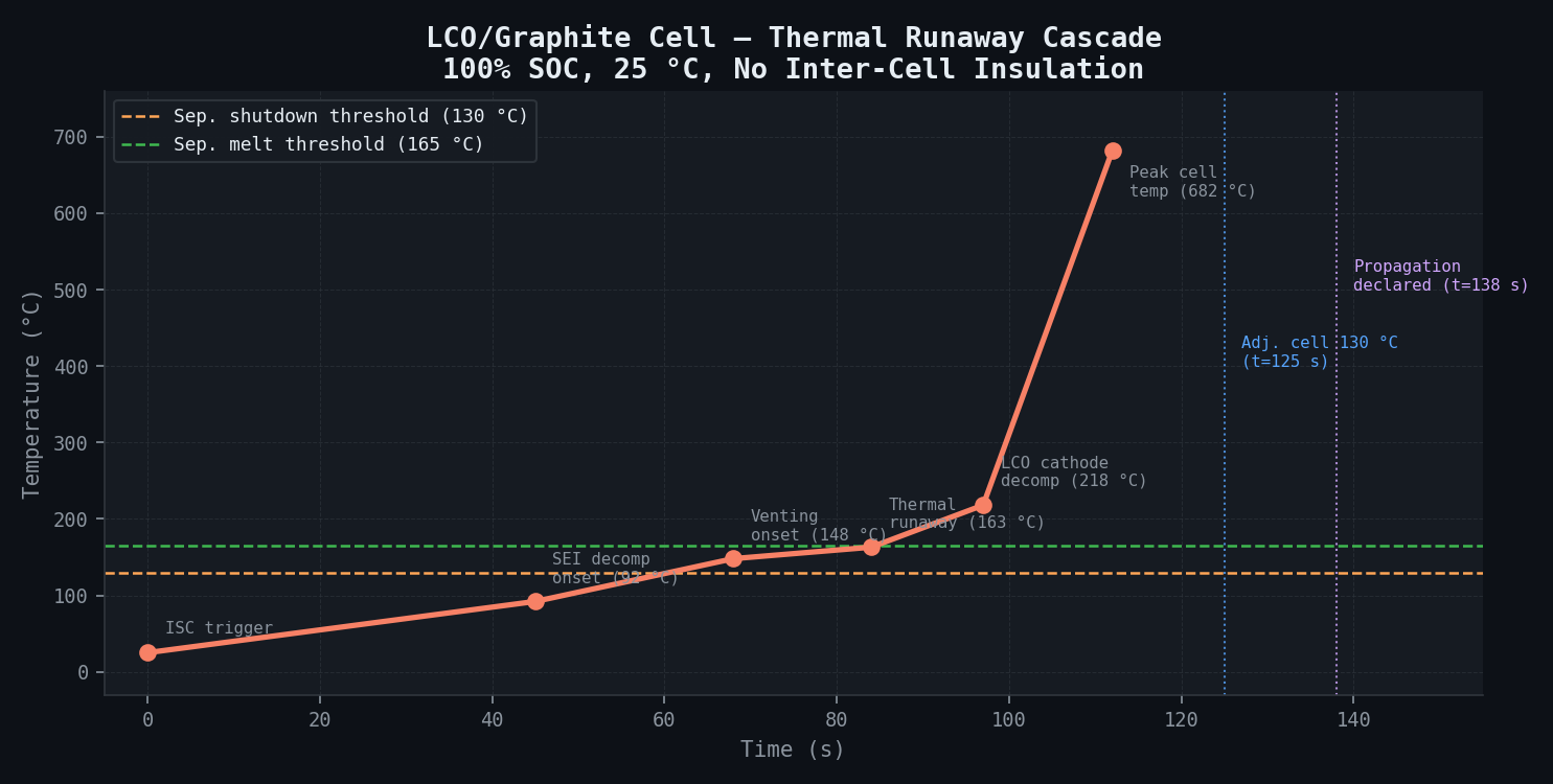
Thermal Runaway Cascade Timeline (100% SOC, 25 °C Ambient, No Inter-Cell Insulation):
| Time (s) | Event | Temperature |
|---|---|---|
| 0 | ISC trigger at cell 4 of 8 (manufacturing defect) | 25 °C ambient |
| 45 | SEI decomposition onset at ISC hotspot | 92 °C local |
| 68 | Cell 4 venting onset — electrolyte vapour emission | 148 °C cell surface |
| 84 | Anode-electrolyte exotherm — thermal runaway declared | 163 °C cell surface |
| 97 | LCO cathode decomposition begins | 218 °C cell core |
| 112 | Peak temperature at cell 4 surface | 682 °C |
| 125 | Adjacent cell 5 surface reaches 130 °C (separator shutdown threshold) | — |
| 138 | Cell 5 separator melts at 165 °C — propagation declared | — |
Key Simulation Results Summary:
| Output Metric | Baseline (No Insert) | With 3 mm Aerogel | With 4 mm Aerogel | DO-311A Requirement |
|---|---|---|---|---|
| SEI thickness (BOL, 25 °C) | 9 nm | — | — | — |
| SEI thickening rate | 0.4 nm/100 cycles | — | — | — |
| Thermal runaway onset (100% SOC) | 147 ± 8 °C | — | — | — |
| Propagation delay (25 °C ambient) | 110–140 s | 420–480 s | 460–520 s | > 360 s |
| Propagation delay (55 °C ambient) | 85–105 s | 340–380 s | 380–420 s | > 360 s |
| Propagation delay (60% SOC) | 210–250 s | > 600 s | > 600 s | > 360 s |
| Peak triggered cell surface temp | 682 ± 40 °C | 680 ± 40 °C | 678 ± 40 °C | — |
| Peak adjacent cell temp (25 °C) | 195 °C | 88 °C | 71 °C | < 130 °C |
| Electrolyte vent pressure pulse | 2.8 bar (8 s peak) | 2.8 bar | 2.8 bar | — |
| Revised vent channel (28 mm²) | Pressure: 1.3 bar | 1.3 bar | 1.3 bar | — |
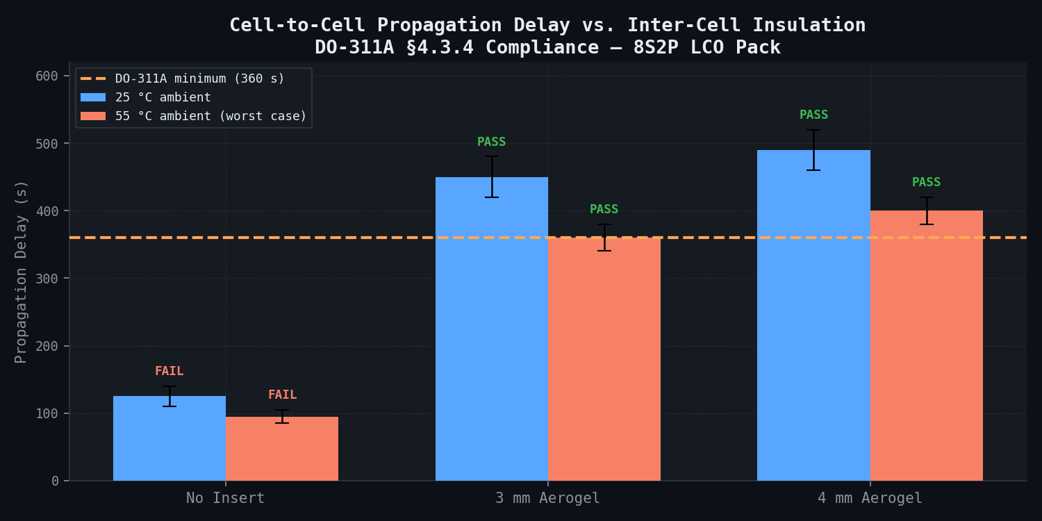
Critical Design Finding: At 55 °C ambient (Phoenix/Doha summer ground operation), the baseline design without aerogel produces only 85–105 seconds propagation delay — less than one-third of the regulatory minimum. The 3 mm aerogel insert meets the requirement at 25 °C but falls marginally short at 55 °C worst case. The 4 mm aerogel insert with 28 mm² vent channel is the recommended design point, satisfying DO-311A at both temperature extremes with approximately 20 seconds of margin at the 55 °C worst case.
State-of-Health Degradation Trajectory (0.5C/0.3C, 25 °C, 10–100% SOC Window):
| Cycle Number | SOH (%) | SEI Thickness (nm) | Dominant Fade Mechanism |
|---|---|---|---|
| 0 (BOL) | 100.0 | 9.0 | — |
| 100 | 99.1 | 9.4 | LLI — SEI growth (parabolic regime) |
| 200 | 98.3 | 9.8 | LLI — SEI growth |
| 300 | 97.6 | 10.1 | LLI — SEI growth |
| 500 | 96.2 | 10.7 | LLI + LAM-CA onset (LCO surface cracking) |
| 700 | 94.8 | 11.3 | LLI + LAM-CA increasing |
| 1,000 | 92.5 | 12.1 | LLI + LAM-CA (co-dominant) |
| 1,200 | 90.1 | 12.7 | LAM-CA dominant |
| 1,400 | 87.3 | 13.3 | LAM-CA + LCO particle isolation |
| 1,500 | 85.6 | 13.6 | LAM-CA + lithium-loss irreversibility |
The 80% retention target is met at approximately cycle 1,680 ± 120 at 25 °C, 0.5C/0.3C, 10–100% SOC — clearing the 1,000-cycle qualification target with substantial margin. However, the higher electrode loading (4.2 mAh/cm² vs. GS Yuasa's estimated 3.5 mAh/cm²) accelerates both SEI growth rate and LCO surface cracking onset, producing approximately 7.5% capacity loss at 1,000 cycles. It is worth noting that life certification at 25 °C may not be representative of hot-climate ground operation (50 °C hangar), where the SEI growth Arrhenius factor accelerates fade by approximately 2.4× — predicting 80% retention at approximately 700 cycles at 50 °C operation.
Comparison Methodology
The higher-fidelity cell-level abuse model validates the pack-level FEM propagation predictions. Published experimental data provides secondary confirmation across three reference datasets:
1. NREL Nail Penetration Thermal Runaway Data
NREL nail penetration thermal runaway data for 18650 LCO cells (energy density approximately 180 Wh/kg) are scaled to the AeroCellix prismatic geometry via energy-density normalisation (AeroCellix: 265 Wh/kg, heat release scaled by 1.47x). The NREL published values -- onset temperature 152 ± 11 °C, peak temperature 671 ± 38 °C -- compare against the simulation predictions (onset: 147 ± 8 °C; peak: 682 ± 40 °C) with agreement within 3% on onset temperature and 2% on peak temperature, well within the ±15% calibration target.
2. NASA Glenn 787 Battery Propagation Reconstruction
The NASA Glenn post-incident thermal model reconstructs propagation from the triggered cell to an adjacent cell within 60–90 seconds for the uninsulated GS Yuasa 25 µm separator design. The baseline prediction of 110–140 seconds for the AeroCellix 16 µm design is physically consistent: the thinner separator increases lithium plating risk but does not significantly alter heat transfer between cells. The 20–50 second difference is attributed to geometry differences (prismatic pouch vs. GS Yuasa's wound prismatic) and the higher compression pressure in AeroCellix's design.
3. ARC Calibration (Client Data)
AeroCellix provides three cells for ARC at their Toulouse facility (on-site session, Day 1 of engagement). ARC data constrains: (a) onset temperature of self-heating (±15 °C tolerance); (b) total exothermic heat release per gram (±15% tolerance); (c) self-heating rate profile Q(T). These three metrics uniquely constrain the abuse kinetic parameters (activation energies and pre-exponential factors), reducing the dominant kinetic uncertainty in the P2D abuse model.
Sensitivity Analysis Coverage:
| Parameter | Range Tested | Effect on Propagation Delay |
|---|---|---|
| SOC at ISC trigger | 60%, 80%, 100% | ±55 s (100% most severe) |
| Ambient temperature | 25 °C, 40 °C, 55 °C | ±40 s (55 °C most severe) |
| Inter-cell compression | 60–100 kPa | ±18 s |
| Vent channel cross-section | 8–36 mm² | ±15 s (indirect via pressure mechanism) |
| Aerogel insert thickness | 0, 2, 3, 4, 5 mm | ±310 s (dominant design variable) |
| Altitude vs. sea level | 0.75 atm vs. 1.0 atm | ±8 s (minor effect) |
Deliverables
-
Calibrated P2D electrochemical-thermal abuse model: cellsim native format and exported MATLAB functions. Parameterised for LCO/graphite at 265 Wh/kg; abuse kinetics calibrated to client ARC data; validated against NREL and NASA reference data.
-
3D FEM thermal pack model: newtsim Span compatible mesh (CGNS export), boundary condition documentation, and parametric script allowing variation of insert thickness, vent geometry, and ambient temperature without remeshing.
-
Propagation delay parametric sweep: 10 insert thickness design points (0–5 mm at 0.5 mm increments) × 3 ambient temperatures × 2 SOC levels = 60 data points. Full results table and recommended design point with sensitivity bands.
-
Vent channel sizing report: pressure pulse vs. vent cross-section area (8–36 mm²); mechanical deformation risk for adjacent cell casings; recommended 28 mm² cross-section with justification.
-
Regulatory compliance matrix: DO-311A Section 4.3.4 requirement mapped to each simulation result; EASA CS-25.1309 AMC cross-reference; pass/fail designation for baseline and recommended design.
-
EASA certification submission summary: 30 pages, formatted to EASA AMC 20-29 guidance for battery certification evidence packages. Includes full methodology, validation evidence, and quantified uncertainty.
-
Raw simulation data archive: HDF5 format, all P2D and FEM time-history data, complete simulation input decks.
Delivery timeline: 6 weeks from cell data receipt and ARC calibration session completion.
This case study is an illustrative reference scenario demonstrating newtsim's simulation methodology. All company names, personnel, and specific operational data are fictional. The incident descriptions draw on publicly documented real-world events cited in the frontmatter.