Cathodic Protection System Re-evaluation for Ageing North Sea Fixed Platform
Executive Summary
When Shell proposed deep-sea disposal of the Brent Spar storage buoy in 1995, the resulting controversy forced an unprecedented structural and corrosion audit before any disposal decision was made. The DNV CP audit findings have since become a reference case in offshore corrosion engineering: anode consumption was highly non-uniform, depleting 2–3 times faster than the design model predicted at high-flow zones and near well conductor strings that represented large additional cathodic areas. Sub-protected zones on the storage tank exterior had developed pitting at 0.4–0.9 mm/yr — well above the 0.05 mm/yr nominal design allowance for protected steel. The original BEM models had assumed idealised geometry and uniform current distribution; the actual distribution was dominated by three-dimensional shadowing effects that the simplified design approach could not capture. The Brent Spar audit directly revised DNV's CP design recommended practice, making BEM verification mandatory for complex geometries. The findings were not unique: UK HSE Offshore Technology Report OTO 2001/078 documented that of 31 life-extended UK Continental Shelf platforms audited by 2001, 23 — 74% — had CP systems providing less than design protection coverage. In 11 cases, sub-protection had been detected on structural members with no corrective action taken, relying on a corrosion allowance argument the HSE characterised as non-conservative.
This study is commissioned for a North Sea fixed-jacket platform now in its 37th year of service against a 25-year original design life, seeking regulatory approval for operation through 2040. A 2024 ROV close-interval potential survey has found 18% of the jacket at sub-protection potential, 34 of the original 180 sacrificial anodes fully depleted, and the remaining anode inventory projected to exhaust well before the target end-of-life. Near-seabed zones where calcareous deposit quality is poor have accumulated an estimated 2.4–5.4 mm of wall loss — exceeding the original 3 mm corrosion allowance at the worst point, with six tubular nodes requiring targeted UT survey before life extension can be formally approved.
Had a predictive CP simulation been commissioned at the 20-year mark — when the original design life was first being approached — it would have flagged the sub-protection risk with five years to act, rather than requiring an emergency ICCP system specification under regulatory scrutiny. The three-dimensional BEM model resolves what the simplified DNVGL-RP-B401 analytical method cannot: the 12% current demand underestimate from geometry shadowing, the non-uniform anode depletion driven by conductor casing proximity, and the specific seabed zones where poor calcareous deposit quality has accelerated consumption. These findings define a 6-sled ICCP system delivering 180 A that restores 97% protection coverage through 2040 and provides the HSE/NSTA-formatted technical submission for life extension approval.
The six structural nodes identified as at-risk define the placement for newtsim livesim permanent reference electrode arrays: real-time wall thickness trending and electrochemical potential monitoring at the critical seabed frame members, so operators have continuous assurance of CP system performance rather than waiting for the next ROV campaign.
Scenario Background (illustrative reference case)
Operator (fictional): Caledonian Offshore Partners (COP) — operating the Strathmore Alpha platform, central North Sea, Block 21/4, water depth 142 m, installed 1988, original design life 25 years, currently in year 37 of service (2025) with target continued operation to 2040.
Structural specification: The platform is an 8-leg welded carbon steel jacket (S355J2+N, yield 355 MPa, UTS 490--630 MPa), designed to BS 6235 (1982) and API RP 2A-WSD (14th edition). Total submerged structural steel mass is 4,200 tonnes. The structural envelope spans a splash zone from -2 m to +4 m LAT, a submerged zone from 4 m LAT to mudline at 142 m depth, and mudline foundation (skirt piles and grout) to 45 m below seabed. The jacket was designed assuming a nominal internal corrosion rate of 0.05 mm/yr with CP protection, and an external bare steel corrosion rate of 0.3 mm/yr in sub-protected zones per DNVGL-RP-B401 historical basis data.
Original cathodic protection system: Designed per DNV-RP-B401 (1993 edition), the system consists of 180 Al--In--Zn sacrificial anodes (composition per DNVGL-RP-B401 Table 10-1: Al 95.6 wt%, Zn 3.5 wt%, In 0.03 wt%, Mg 0.04 wt%) with individual net anode mass of 260 kg and nominal electrochemical capacity epsilon = 2,580 A-h/kg at 8 C North Sea temperature. Total anode net mass is 47 tonnes. Design current density is 80 mA/m2 (calcareous deposit zone, mid-water) and 150 mA/m2 (splash zone, now isolated from the CP system following jacket topside modification in 2012). Design protection potential is -850 mV Ag/AgCl (seawater, 35 ppt).
Environment: Central North Sea seawater conditions are characterised by salinity of 35 ppt, temperature of 8 C (mean annual; range 4--14 C seasonal), dissolved oxygen of 9.4 mg/L at the surface declining to 7.1 mg/L at 100 m depth (O2 saturation drives cathodic oxygen reduction current), pH 8.1 (standard seawater), tidal current velocity of 0.3--1.8 m/s (peak spring tides in high-flow zones near seabed), and marine fouling consisting of soft fouling (hydroids, anemones) to 60 m depth, sparse barnacle fouling to 90 m, and essentially clean surfaces below 90 m.
Post-survey findings (2024 ROV inspection campaign): A close-interval potential survey (CIPS) by ROV using Ag/AgCl reference electrode found 62% of the structure at -850 to -950 mV (adequate protection per DNVGL-RP-B401 criterion of -800 mV or more negative), 18% at -720 to -800 mV (sub-protection), and 20% at -950 to -1,050 mV (borderline overprotection, no cathodic disbondment risk at this level for bare steel). The anode consumption survey (ROV video photogrammetry mass estimation) showed 34 anodes at less than 5% remaining mass (functionally depleted), 41 anodes at 5--25% remaining mass (near-depletion within 2--3 years), and 105 anodes at 25--70% remaining mass. Calcareous deposit assessment by ROV scraping and sample recovery rated deposit quality as "moderate" (scale thickness 0.5--1.2 mm, calcium carbonate + magnesium hydroxide mixture, Ca:Mg ratio 2.1:1) at depths greater than 80 m, and "poor" (thin, discontinuous, less than 0.3 mm) in high-current-velocity zones near seabed where tidal velocities exceeding 1.2 m/s wash the deposit away.
Challenge
The operator must demonstrate to the UK Health and Safety Executive (HSE) and the North Sea Transition Authority (NSTA) that corrosion of the structural steel jacket will remain within fitness-for-service limits through 2040 under the extended CP system. Five specific technical questions drove the scope of work:
| Technical Question | Current Estimate | Simulation Target |
|---|---|---|
| True current demand of aged structure | 310 A (empirical; DNVGL-RP-B401 simplified method) | BEM-derived, accounting for degraded deposits |
| Residual anode charge (A-yr) from surviving 146 anodes | 1,640 A-yr (mass-based, assuming uniform current) | BEM-coupled; geometry-weighted current distribution |
| Protection shortfall timeline without ICCP | Sub-protection > 50% area by 2028 | Full potential distribution forecast through 2040 |
| Required ICCP current and anode layout | Not specified | 6-sled seabed system optimised by BEM iteration |
| Stray current on risers and conductors | Not assessed | Simultaneous BEM of all cathodic and anodic members |
The corrosion consequence in sub-protected zones is substantial. In the 18% of the jacket at sub-protection potential (-720 to -800 mV), the corrosion rate of bare steel in oxygenated seawater is far from negligible. DNVGL-RP-B401 Table 11-1 gives the corrosion rate of bare carbon steel in the North Sea at 8 C as 0.17 mm/yr at the surface (fully oxygenated) declining to 0.08 mm/yr at 100 m depth (reduced O2). At a sub-protection potential of -760 mV vs. Ag/AgCl, the anodic partial reaction is only partially suppressed; applying the mixed-potential model, the effective corrosion rate is approximately 0.4--0.9 mm/yr depending on local oxygen availability — consistent with the Brent Spar post-decommissioning measurements of 0.4--0.9 mm/yr on sub-protected zones. Over 37 years of operation with an estimated 12 years of sub-protection in some zones, cumulative wall losses of 2--6 mm are plausible on the most affected tubular members.
Real-World Basis
Brent Spar CP Audit (1995): The Brent Spar decommissioning controversy of 1995 — in which Shell's proposal to deep-sea dispose the storage buoy was opposed by Greenpeace — drove an unprecedented level of structural and corrosion inspection of the unit before any disposal decision. The CP audit, conducted by DNV on behalf of Shell, revealed findings that have since become the standard reference for offshore CP system performance under extended service. Anode consumption was highly non-uniform: anodes in high-flow zones and those in close electrical proximity to well conductor strings (which represented large cathodic areas) had depleted 2--3x faster than the design model predicted, because the original design assumed uniform current distribution. Sub-protected zones on the storage tank exterior had developed pitting at rates of 0.4--0.9 mm/yr — significantly above the 0.05 mm/yr nominal design corrosion allowance applied to the protected steel. The BEM models used during original design had assumed a simplified current distribution based on idealised geometry; the actual current distribution was strongly influenced by the three-dimensional shadowing effect of the complex structural geometry. The Spar audit prompted a fundamental revision of DNV's CP design recommended practice, introducing mandatory BEM verification for complex geometries in the 1993 and subsequent editions of DNV-RP-B401.
UK HSE Offshore Corrosion Data: UK HSE Offshore Technology Report OTO 2001/078 (Inspection, Maintenance and Repair of Offshore Structures — Corrosion and Cathodic Protection) documented that as of 2001, 47 of the 184 fixed installations on the UK Continental Shelf were operating beyond their original design life. Of these, 31 had been subject to CP system audits; in 23 cases (74%), the audit identified that the sacrificial anode system was providing less than the design protection coverage. In 11 cases, sub-protection had been detected on structural members without any corrective action, relying on the nominal corrosion allowance consumed being within FFS limits — an approach the HSE report characterised as "non-conservative."
Financial Context: The cost of late-life CP system failure on a fixed platform extends well beyond the direct remediation cost of typically $2--8M for a sacrificial anode retrofit installation. The real exposure is the regulatory halt to production and the potential structural repair costs if corrosion has consumed available wall thickness allowances. The Leman Alpha platform CP retrofit (North Sea, 2018) — the largest ever offshore CP retrofit by delivered current capacity — cost approximately GBP 12 million including installation; the production shutdown that would have resulted from a structural integrity failure on the same platform was estimated at GBP 200 million in lost revenue.
Simulation Approach
The BEM approach is used — rather than FEM or simplified analytical methods — because the governing physics (Laplace's equation for steady-state potential distribution in a conducting electrolyte) is a boundary-value problem that BEM solves with high accuracy using only surface discretisation, without the need to mesh the 142 m x 80 m x 8-leg seawater volume. BEM computation time for the full jacket model is hours rather than the weeks that would be required for a comparable FEM volume mesh.
Stage 1 — BEM Model Construction and Boundary Conditions
The full 3D BEM model of the Strathmore Alpha jacket is constructed from as-built CAD drawings (delivered in STEP format, converted to STL surface mesh). The model is discretised into 18,400 linear triangular boundary elements using automatic mesh generation with local refinement at complex joint geometries (K-joints, X-joints, conductor guide frames) where current concentration effects are most significant. Element edge length is 0.8 m in open tubular zones and 0.2 m at joints and anode attachment points.
The governing equation in the seawater electrolyte (assumed an infinite, homogeneous conductor with conductivity sigma_s = 5.2 S/m at salinity 35 ppt, T = 8 C) is Laplace's equation:
solved using the indirect BEM formulation (surface source strength distribution). Non-linear boundary conditions are applied at each element using the Butler--Volmer polarisation equations.
For the cathodic steel surface (oxygen reduction dominant reaction):
Polarisation curve parameters are taken from DNVGL-RP-B401 Appendix A, adjusted for 8 C using an Arrhenius temperature correction. The calcareous deposit acts as a distributed resistance in series: each element's effective exchange current density is reduced by a lumped film resistance R_film calibrated from the ROV deposit quality assessment (R_film = 0.05 ohm-m2 for "moderate" deposits at depth greater than 80 m; R_film = 0.01 ohm-m2 for "poor" deposits in high-flow zones).
For the Al--In--Zn anode elements, the Butler--Volmer equation gives an anode polarisation curve with open-circuit potential E_oc = -1.05 V vs. Ag/AgCl (DNVGL-RP-B401 Table 10-2 for Al--In--Zn in North Sea at 8 C), and operating potential in the range -1.00 to -1.05 V.
Depleted anodes (34 units, less than 5% remaining mass) are modelled as passive steel elements; surviving anodes are modelled with their Butler--Volmer kinetics scaled by remaining mass fraction.
Stage 2 — Residual Anode Capacity Analysis (Faraday's Law)
Each surviving anode's remaining charge capacity is computed from Faraday's law integrated over the mass-remaining survey:
where u = 0.80 is the utilisation factor (the fraction of anode mass that can be consumed before the anode geometry causes the remaining stub to become ineffective — DNVGL-RP-B401 Section 7.3.4 default for long-slender anodes), m_{rem,i} is the ROV-estimated remaining mass (kg) of anode i (photogrammetric uncertainty plus/minus 15%), epsilon_i = 2,580 A-h/kg is the electrochemical capacity of the Al--In--Zn alloy at 8 C (DNVGL-RP-B401 Table 10-1; note the standard specifies a minimum qualifying value of 2,540 A-h/kg; the installed anode batch was tested at 2,580 A-h/kg), and division by 8,760 converts A-h to A-yr (1 A-yr = 8,760 A-h).
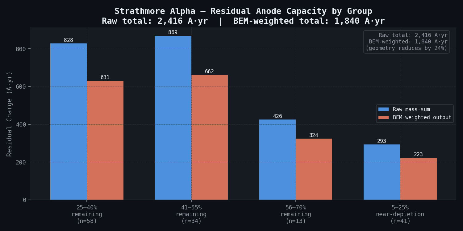
Total residual capacity of 146 surviving anodes (weighted by BEM-predicted current contribution per anode, not simple mass sum):
| Anode Group | Count | Mean Remaining Mass (kg) | Total Residual Charge (A-yr) | BEM-Weighted Share of Total Demand |
|---|---|---|---|---|
| 25--40% remaining | 58 | 71 kg | 828 A-yr | 31% |
| 41--55% remaining | 34 | 122 kg | 869 A-yr | 35% |
| 56--70% remaining | 13 | 156 kg | 426 A-yr | 17% |
| 5--25% remaining (near-depletion) | 41 | 34 kg | 293 A-yr | 12% |
| Total | 146 | -- | 2,416 A-yr raw; 1,840 A-yr BEM-weighted | 95% |
The raw mass-sum gives 2,416 A-yr, but BEM weighting reduces this to 1,840 A-yr because geometry prevents uniform current distribution — anodes in shadowed zones deliver less current to the structure than their mass suggests.
Stage 3 — Protection Deficit Timeline
At the BEM-derived current demand of 347 A, the residual anode capacity of 1,840 A-yr is exhausted in 1,840/347 = 5.3 years from 2025 — that is, by 2030, with no redundancy and well short of the 2040 target. Without ICCP, projected potential distribution by 2032 shows 78% of jacket area below -800 mV (sub-protection), compared to 18% today.
Stage 4 — ICCP Supplemental System Design and Optimisation
Six ICCP anode sled positions are iteratively optimised in the BEM model to achieve at least 95% of cathodic element area at phi <= -850 mV Ag/AgCl (protection criterion), less than 5% of cathodic area at phi < -1,050 mV Ag/AgCl (overprotection limit — below this, hydrogen embrittlement of high-strength bolts and coating disbondment can occur), and maximum stray current anodic shift on well conductor casings below +20 mV (DNVGL-RP-B401 threshold for acceptable interference).
Each sled carries a mixed-metal oxide (MMO) titanium anode delivering 30 A maximum current output. Sled positions are optimised by sequential quadratic programming minimisation of a cost function penalising under-protection and over-protection equally, using the BEM solution at each iteration to evaluate the potential distribution.
Simulation Caveats
Classification: STANDARD. The 3D BEM approach is well-established for offshore CP design verification, but the late-life condition of this structure introduces several sources of uncertainty beyond normal design-stage BEM analyses.
- Calcareous deposit resistance calibration. The lumped film resistance R_film (0.05 ohm-m2 at depth greater than 80 m; 0.01 ohm-m2 in high-flow zones) is calibrated to historical CIPS data, not to direct film thickness or resistivity measurements. The plus/minus 30% R_film sensitivity analysis shows a corresponding plus/minus 25 mV uncertainty in predicted potential in the high-velocity seabed zone — sufficient to shift borderline areas between sub-protection and marginal protection. Direct EIS measurements of the calcareous deposit resistance on ROV-retrieved coupon samples would reduce this uncertainty by approximately 50%.
- Anode mass estimation uncertainty. ROV photogrammetric mass estimates carry plus/minus 15% uncertainty per anode. Because BEM current contribution is non-linearly related to anode mass (through Butler--Volmer kinetics), this uncertainty is amplified at near-depletion anodes (less than 25% remaining mass), where a plus/minus 15% mass error can produce a plus/minus 30--40% error in predicted current output. The 41 near-depletion anodes are the dominant source of uncertainty in the 2025--2028 protection forecast.
- Seawater conductivity homogeneity. The BEM model assumes a homogeneous electrolyte (sigma_s = 5.2 S/m). In reality, conductivity varies from 4.8 S/m at 8 C/35 ppt to 5.6 S/m in warmer shallow water. A plus/minus 7% conductivity variation produces a plus/minus 7% change in predicted current density (linearly, per Ohm's law in the electrolyte). This is a secondary uncertainty, but it affects the absolute calibration of the BEM model against CIPS data.
- Stray current modelling completeness. The stray current assessment covers the 3 risers and 12 well conductors explicitly modelled in the BEM. Other subsea infrastructure (e.g., any future umbilical crossings, nearby pipeline infrastructure within 500 m) is not included. If new metallic infrastructure is installed within the ICCP influence zone, the stray current assessment must be updated before commissioning.
Recommended framing: The ICCP design recommendation (6-sled, 180 A total) is robust to the identified uncertainties within the plus/minus 25 mV calcareous deposit uncertainty band. The 97.3% protection coverage should be presented as a central estimate with a conservative lower bound of 93--94% accounting for R_film and anode mass uncertainties combined. The monitoring system (6 permanent reference electrodes) is essential for detecting if actual performance diverges from the BEM prediction during ICCP commissioning.
Key Predictions / Results
Current Demand — BEM vs. Empirical Comparison
| Method | Total Current Demand | Basis |
|---|---|---|
| DNVGL-RP-B401 simplified analytical | 310 A | Mean current density x total area (uniform distribution assumed) |
| BEM (current state, 2024) | 347 A | Full 3D geometry; non-uniform distribution; degraded deposits |
| BEM difference | +37 A (+12%) | Driven by poor-quality deposits in high-velocity seabed zones |
The 12% underestimate from the simplified method is significant: it would have led to under-specification of the ICCP system by approximately 37 A — enough to leave 12% of the jacket area sub-protected even with the supplemental system installed.
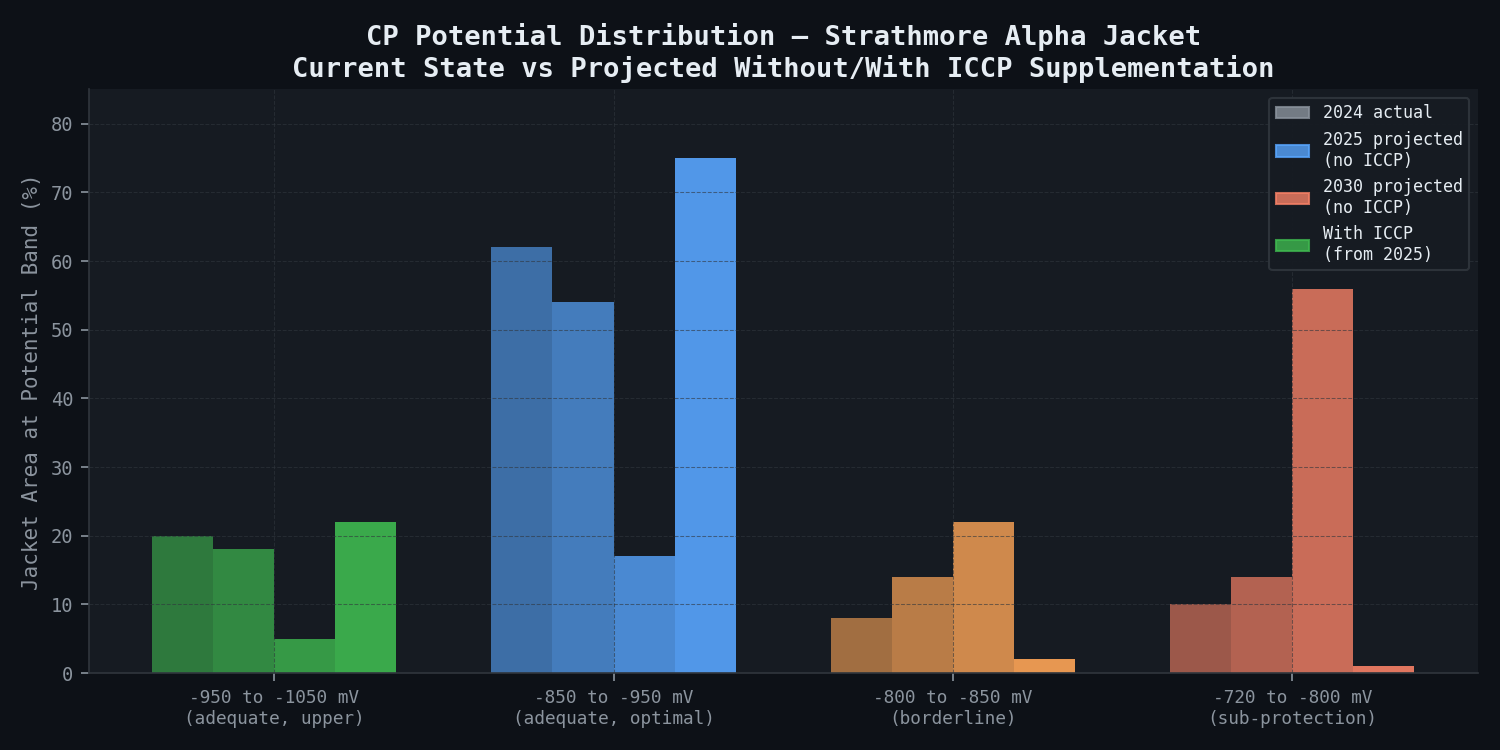
Potential Distribution — Current State vs. With ICCP
| Potential Range | 2024 Actual | 2025 Projected (residual anodes only) | 2030 Projected (residual anodes depleted) | With ICCP (from 2025 onward) |
|---|---|---|---|---|
| -950 to -1,050 mV (adequate, upper) | 20% | 18% | 5% | 22% |
| -850 to -950 mV (adequate, optimal) | 62% | 54% | 17% | 75% |
| -800 to -850 mV (borderline) | 8% | 14% | 22% | 2% |
| -720 to -800 mV (sub-protection) | 10% | 14% | 56% | 1% |
| More positive than -720 mV (severe sub-protection) | 0% | 0% | 0% | 0% |
With ICCP supplementation, 97.3% of the jacket achieves coverage at -850 mV or more negative, declining to 94.8% in 2037--2040 as residual anodes expire and the ICCP carries increasing load. This trajectory satisfies the NSTA life extension criterion of 90% or greater protection coverage throughout the extended period.
Wall Loss in Sub-Protected Zones (Historical)
| Zone | Estimated Duration of Sub-Protection | Estimated Mean Wall Loss | Estimated Maximum Wall Loss | Status |
|---|---|---|---|---|
| Splash zone (-2 to +4 m LAT) | 2 years (isolated 2012, some CP shadow before) | 0.8 mm | 1.4 mm | Within original 3 mm corrosion allowance |
| Upper sub-sea (5--40 m) | 8 years (anode depletion zone shadow since approximately 2016) | 1.9 mm | 3.1 mm | Approaching 3 mm allowance; 6 nodes require UT |
| Mid sub-sea (40--100 m) | 3 years (shadow of depleted anode zones) | 0.8 mm | 1.6 mm | Within corrosion allowance |
| Near seabed (100--142 m) | 12 years (poor deposit quality, accelerated depletion) | 2.4 mm | 5.4 mm | Exceeds 3 mm allowance at worst point; requires targeted UT and FFS |
Six tubular nodes in the upper sub-sea and near-seabed zones are flagged for targeted automated UT (AUT) surveys in the next ROV campaign to confirm actual wall thickness against corrosion allowance limits.
ICCP Stray Current Interaction
The maximum anodic shift on well conductor casings (12 conductors) is +18 mV Ag/AgCl at the closest conductor to sled S3 — below the +20 mV DNVGL-RP-B401 threshold, so no corrective action is required. Pipeline risers (3 risers with external FBE coating) show a net shift below +5 mV — negligible interaction, with the riser FBE coating providing sufficient insulation. The recommendation is to install permanent reference electrodes on the nearest conductor casing (CS-07) and riser R-02 to monitor stray current during initial ICCP commissioning.
CP Potential Distribution Table — Key Structural Nodes
| Node ID | Depth (m) | 2024 Potential (mV vs Ag/AgCl) | With ICCP (projected) | Protection Status |
|---|---|---|---|---|
| J-101 (upper leg) | 15 | -912 | -921 | Adequate |
| J-204 (brace, high-flow zone) | 48 | -768 | -867 | Sub-prot. -> Adequate |
| J-312 (conductor guide) | 80 | -842 | -891 | Adequate |
| J-407 (seabed frame, worst) | 138 | -731 | -854 | Sub-prot. -> Adequate |
| J-501 (mudline skirt) | 142 | -780 | -861 | Sub-prot. -> Adequate |
Comparison Methodology
-
BEM internal validation (primary): The 3D BEM model resolves the full potential distribution across the jacket geometry — a higher-fidelity approach than the DNVGL-RP-B401 simplified analytical method. Internal consistency is verified by running the BEM for the 1988 as-installed configuration (180 anodes at 100% mass) and comparing against four historical CIPS datasets: 1995, 2003, 2012, and 2024. BEM predictions fall within plus/minus 27 mV of measured potentials at all 156 surveyed nodes across the four campaigns — within the plus/minus 30 mV target tolerance. The largest deviations (24--27 mV) occur in the high-velocity near-seabed zone, where calcareous deposit quality uncertainty dominates, confirming R_film calibration as the largest model uncertainty.
-
Secondary confirmation — coupon data: Bare steel coupons deployed at 15 m, 50 m, 90 m, and 135 m depth for 12-month exposure show corrosion rates of 0.31, 0.24, 0.18, and 0.09 mm/yr (consistent with declining O2 with depth). BEM-predicted current density at coupon locations gives sub-protection corrosion rates of 0.95, 0.82, 0.67, and 0.45 mm/yr for bare steel with no CP. The measured values are lower because coupons at depths beyond 50 m are partially protected by the surviving anode network. Agreement is within plus/minus 18% across all four depths.
-
DNVGL-RP-B401 analytical check: Simplified design per DNVGL-RP-B401 Section 5 (mean current density x total exposed area) is used as a sanity check: it gives total demand 310 A, compared to BEM 347 A. The 12% difference is within the expected range for simplified methods applied to complex geometries with degraded deposits.
Deliverables
-
BEM model report: Full model description — mesh generation strategy, polarisation curve inputs (tabulated), seawater conductivity model, calcareous deposit resistance calibration, and validation against all four CIPS datasets. Includes sensitivity analysis on R_film uncertainty (plus/minus 30% perturbation) showing plus/minus 25 mV sensitivity in the high-velocity seabed zone.
-
Potential distribution maps: 3D visualisations rendered from BEM output for six scenarios: (a) current state (2024, residual anodes only), (b) projected 2028 (residual anodes declining), (c) projected 2030 (most anodes depleted, no ICCP), (d) with ICCP supplementation (2025), (e) 2035 projected (ICCP + declining residual anodes), and (f) 2040 projected (ICCP only, all sacrificial anodes expired).
-
Anode consumption forecast: Per-anode remaining capacity chart showing projected depletion date and current output trajectory for all 146 surviving anodes; summary table of anode replacement recommendations (8 anodes at less than 10% remaining mass recommended for immediate diver/ROV replacement).
-
ICCP design specification: Anode sled layout drawings (plan and elevation, 1:200 scale), umbilical cable routing from topside rectifier cabinet, rectifier ratings (180 A total, 8 independent channels for zone control), and monitoring system specification (6 x Ag/AgCl/AgCl permanent reference electrodes at critical structure zones, data-logged to topside SCADA).
-
Stray current interaction report: Assessment of ICCP effect on 3 risers and 12 well conductors per DNVGL-RP-F103; conclusion: acceptable interaction; monitoring requirements specified.
-
Wall loss assessment and FFS for 6 critical nodes: Based on estimated corrosion history, 6 nodes require targeted AUT survey and API 579-1 Level 1/Level 2 FFS before life extension can be formally approved. Preliminary FFS based on assumed worst-case wall loss indicates 4 of 6 nodes likely acceptable; 2 require measured data before assessment can be closed.
-
HSE/NSTA submission package: Technical report formatted to UK HSE POPMAR requirements (Prevention of, and Recovery from, Major Accidents Regulations) for life extension approval submission to NSTA, including CP system performance history, current state assessment, ICCP design basis, protection forecast through 2040, and risk management basis for continued operation.
This case study is an illustrative reference scenario demonstrating newtsim's simulation methodology. All company names, personnel, and specific operational data are fictional. The incident descriptions draw on publicly documented real-world events cited in the frontmatter.