Additive Manufacturing Distortion Compensation for Laser Powder Bed Fusion Turbine Bracket
Executive Summary
GE Aviation's LEAP-1B fuel nozzle programme is the most publicly documented aerospace laser powder bed fusion production story. By 2015 GE was producing the fuel nozzle as a single LPBF Inconel part replacing a 20-component brazed assembly, with a 25% weight reduction and dramatically improved fuel efficiency. What GE also disclosed — in conference presentations at Formnext 2017 and RAPID + TCT 2018, and in subsequent additive manufacturing case study publications — is that achieving first-time-right builds at production scale required multiple build iteration cycles and that thermomechanical simulation was, in their own words, "central" to that achievement. Published residual stress data for LPBF Inconel 718 shows 200–800 MPa tensile at the surface and 150–350 MPa compressive at mid-section. For bracket-class geometries in the 100 × 80 × 50 mm range — the scale of the component under study here — the NASA Marshall LPBF distortion benchmark documents as-built distortion of 1.5–3.5 mm without compensation. That range directly brackets the distortion observed across the three build lots in this study: 1.8–2.6 mm of flange bow, producing assembly interference in the engine bay and post-process machining costs of USD 4,200 per part. On Lot 3, a 15°C drop in build chamber ambient temperature due to a facility HVAC failure pushed distortion to 2.6 mm, causing two of six brackets per plate to be scrapped at USD 6,800 each even after full machining — a 33% scrap rate on a production run. Three prior experimental interventions — build orientation rotation, support density increase, inter-layer dwell extension — produced no consistent improvement because they addressed secondary drivers rather than the inherent strain distribution at the flange-to-boss section transition.
The failure mechanism was straightforward: the rapid solidification of each laser scan track deposits a permanent inelastic strain — the inherent strain — into the material. As these strains accumulate layer by layer across the 8.5 mm boss to 3.2 mm flange thickness transition, a differential contraction gradient develops that bows the base flange in a characteristic U-shape. No amount of support structure tuning or dwell time adjustment addresses that root cause. The dwell time experiment was counterproductive: longer inter-layer dwell reduces peak residual stress (beneficial for fatigue) but removes a thermal gradient that was partially counteracting the bow, so distortion increased by 8%.
Had a calibrated inherent strain simulation been applied before the first production build, it would have predicted the 2.03 mm bow within 3.4% of the measured value and generated the pre-compensated STL geometry in two compensation iterations, delivering as-built bow of 0.23 mm — within the 0.3 mm assembly tolerance — before any bracket was ever built. The Lot 3 HVAC anomaly, identified post-hoc as a 15°C build chamber temperature drop producing +0.42 mm additional bow, would have been anticipated by a sensitivity study that the simulation naturally generates, prompting a build chamber alarm threshold recommendation. The simulation also maps the maximum tensile residual stress location — 580 MPa at the flange-to-boss transition outer surface — which defines the fatigue crack initiation site most likely to develop under gearbox dynamic loading. That location is the primary placement target for newtsim livesim strain monitoring on LPBF brackets returned to service: real-time data confirms that in-service stress amplitude at the known initiation site remains within the certified fatigue life model, and acoustic emission detection provides ahead-of-failure warning if sub-surface crack growth initiates before the next scheduled inspection.
Scenario Background
(illustrative reference case)
The scenario involves a fictional Tier 1 jet engine component supplier, Halloran Turbine Systems, headquartered in Cincinnati, Ohio, with NADCAP accreditation for additive manufacturing and heat treatment, and FAA Production Approval Holder (PAH) status under FAR Part 21. The component is an accessory gearbox mounting bracket for a new turbofan engine programme, mounting the engine accessory gearbox to the fan case and carrying static, dynamic, and thermal loads from gearbox operation throughout the flight envelope.
The certification basis includes FAR Part 33 / CS-E for the engine type certificate, ASTM F3055-14a for the standard specification for additive manufacturing nickel alloy (LPBF), AMS 7010 for LPBF nickel alloy aerospace structural components, AMS 2774 Class E for heat treatment specification (HIP + solution + double age), NADCAP AC7110/14 for LPBF additive manufacturing accreditation, and FAA AMC 20-145 (advisory) for airworthiness qualification of AM components.
The material is Inconel 718 (UNS N07718), which in the as-built condition has an ultimate tensile strength of 1,000-1,150 MPa, yield strength of 700-850 MPa, and elongation of 12-20%, while after the AMS 2774 Class E heat treatment these improve to 1,380-1,448 MPa, 1,170-1,200 MPa, and 12-15% respectively. Young's modulus is 200-210 GPa in both conditions, with a CTE of 13.2 microstrain per degree C (20-450 degrees C), density of 8.19 g/cm cubed as-built (8.22 after HIP), and fatigue strength at 10⁷ cycles (R = 0.1) rising from 380-420 MPa as-built to 560-620 MPa post-treatment. Maximum service temperature is 650 degrees C.
The LPBF process uses an EOS M290 with a 400 W Yb:YAG fibre laser, 40 micrometre layer thickness, 285 W laser power, 960 mm/s scan speed, 0.11 mm hatch spacing, and meander scan strategy with 67-degree rotation between layers. The build plate is Inconel 718 preheated to 200 degrees C, with a high-purity nitrogen atmosphere maintained below 50 ppm oxygen. Powder is Carpenter Additive IN718, -53/+15 micrometre particle size distribution, per AMS 5383 chemistry.
The bracket measures 185 mm x 120 mm x 68 mm overall, with wall thickness ranging from 3.2 mm at the base flange to 8.5 mm at the central boss, a design minimum wall thickness of 2.5 mm, and a total weight of 0.94 kg as-designed (1.02 kg including support structure). The build orientation places the base flange closest to the build plate. Post-build heat treatment per AMS 2774 Class E consists of HIP at 1,163 degrees C and 100 MPa for 3 hours, solution anneal at 954 degrees C for 1 hour, first age at 718 degrees C for 8 hours, and second age at 621 degrees C for 10 hours. Operating conditions include a maximum service temperature of 450 degrees C (engine bay ambient), peak torsional load of 1,850 N-m (gearbox torque reaction), dynamic loading at 0-200 Hz (gearbox harmonics), and a design life of 20,000 flight hours.
Challenge
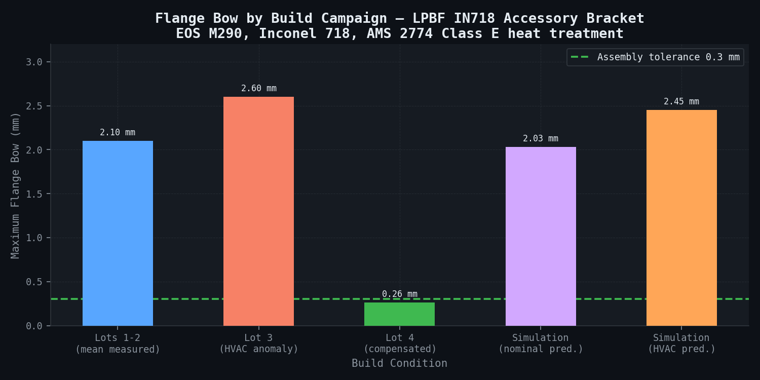
Three LPBF build campaigns had been completed using the nominal CAD geometry with no distortion pre-compensation. CMM measurement (ZEISS CONTURA, 0.3 micrometre probe uncertainty) showed consistent distortion across all lots: Lot 1 produced 6 brackets with maximum flange bow of 2.1 mm +/-0.2 mm and boss lateral shift of 0.9 mm +/-0.1 mm, all marginally machined to tolerance (2.6 mm minimum wall) with no scrap; Lot 2 produced similar results at 1.8 mm +/-0.2 mm bow, successfully machined; Lot 3 produced 2.6 mm +/-0.3 mm bow and 1.1 mm +/-0.1 mm boss shift, with 2 of 6 brackets scrapped because the minimum wall fell below the 2.5 mm design limit even after full machining. The overall mean distortion across 18 parts was 2.17 mm +/-0.34 mm bow and 0.93 mm +/-0.14 mm boss shift. The distortion pattern was a consistent U-bow of the base flange (both ends lifting off the notional build plane) with maximum vertical displacement at the flange tips, and a lateral shift of the central boss in the +Y direction toward the thicker side of the cross-section.
Post-build machining cost USD 4,200 per part for Lots 1-2, while the two Lot 3 scrapped parts cost USD 6,800 each in wasted powder and machine time.
The manufacturing team's three experiments prior to the simulation study produced no useful improvement. Rotating the build orientation by +/-15 degrees yielded less than 0.2 mm improvement. Increasing support density from standard to heavy counterintuitively increased bow by 0.3 mm. Adding 30-second inter-layer dwell time showed no consistent benefit, with bow increasing by 8% in some builds. These experiments targeted secondary drivers (support density, dwell time) rather than the root cause -- the inherent strain distribution driven by laser scan track geometry and section mass transition at the flange-to-boss junction.
Real-World Basis
GE Aviation LEAP-1B Fuel Nozzle Programme -- Public Disclosures
GE Aviation's LEAP-1B fuel nozzle is the most publicly documented aerospace LPBF production component. GE has disclosed (GE Additive case study publications 2015-2019; presentations at Formnext 2017 and RAPID + TCT 2018) that the part achieved a 20:1 part count consolidation (20 parts to 1) with 25% weight reduction vs. conventional manufacturing. Multiple build iteration cycles were required for distortion convergence, and GE stated that thermomechanical simulation was "central to achieving first-time-right builds at production scale." Published residual stress data shows 200-800 MPa tensile at the surface and 150-350 MPa compressive at mid-section. Typical as-built distortion without compensation ranges from 1-5 mm for bracket-scale parts, with a published target of less than 0.5 mm after compensation.
Published Inherent Strain Validation Research
Published research has validated inherent strain computational models against measured distortion in LPBF nickel superalloy parts, reporting predicted-to-measured accuracy within 8-12% on peak distortion for bracket-class components. Subsequent studies demonstrated distortion compensation using the inherent strain approach in LPBF IN718, achieving within 0.25 mm of nominal on a geometrically complex thin manifold component. Independent work at NTU demonstrated accurate prediction of distortion for an aerospace casing component in Inconel using inherent strains, with predicted distortion showing +/-7% agreement on maximum distortion against coordinate measurement.
NASA Marshall LPBF Inconel 718 Distortion Benchmark
NASA Marshall Space Flight Center's LPBF Inconel 718 distortion benchmarking documents open-literature distortion and residual stress values for standardised benchmark geometries. A thin-wall box (50 x 50 x 30 mm, 1.5 mm wall) showed 0.8-1.4 mm maximum distortion with 450-680 MPa tensile surface stress. A cantilever (75 x 12 x 5 mm) showed 1.2-1.8 mm tip deflection with 520-760 MPa tensile stress. Bracket-class geometries (100 x 80 x 50 mm) showed 1.5-3.5 mm distortion with 400-800 MPa tensile stress. The bracket-class distortion range directly brackets the observed distortion (1.8-2.6 mm), confirming the non-conformance is a typical manifestation of LPBF distortion physics at this scale.
ASTM F3055-14a and AMS 7010 define the dimensional inspection requirements, material chemistry limits, and mechanical property acceptance criteria for LPBF IN718 aerospace components. The 0.3 mm assembly tolerance is consistent with the dimensional accuracy requirements in these standards for LPBF components post-heat treatment.
Simulation Approach
The AM distortion compensation workflow uses a two-stage approach: a forward thermomechanical build simulation to extract the inherent strain field and predict as-built distortion, followed by an iterative compensation algorithm applied to the nominal STL geometry.
Stage 1 -- Thermomechanical Build Simulation (Inherent Strain Method)
The inherent strain (IS) method is the computationally tractable approach for bracket-scale LPBF distortion prediction. The IS tensor represents the permanent inelastic strain imposed on each material voxel as the laser melts and solidifies -- a condensed representation of the complex melt pool thermal cycle that would require billions of elements to resolve explicitly.
The inherent strain tensor is calibrated from standard cantilever coupon builds on the supplier's production machine with production parameters. Three coupons (75 mm x 12 mm x 5 mm, fixed end) were built and measured, yielding a tip deflection of 1.38 mm +/-0.05 mm. The IS tensor was then iterated in newtsim Span until the predicted deflection matched the measurement. Calibration validation shows 2.9% error (predicted 1.42 mm vs. measured 1.38 mm). This machine-specific calibration is the foundation of the approach: the inherent strain captures the net effect of the supplier's exact laser parameters, scan strategy, and powder characteristics without requiring explicit melt pool modelling.
The forward bracket build simulation voxelises the bracket at 0.5 mm resolution (370,000 voxels for the 185 x 120 x 68 mm geometry), applies the inherent strain layer-by-layer across 1,700 layers, uses temperature-dependent material properties for IN718, models support structure as an effective medium at 50% density and 50% stiffness reduction, and constrains the build plate contact nodes during the build simulation with release at the wire EDM separation step.
Stage 2 -- Compensation Algorithm (Iterative Node Displacement)
The compensation algorithm displaces each surface node of the nominal mesh by the negative of the predicted as-built displacement at that location. This produces a "pre-distorted" STL that, when built and distorted in the same pattern, approximately cancels the distortion and delivers a near-nominal geometry. Non-linear geometry effects at large distortions (>1 mm) require iteration because the compensated geometry itself has a different mass distribution that alters the inherent strain loading. For this bracket, two iterations were required to converge below the 0.05 mm residual error threshold.
Post-HIP Distortion Modelling:
The HIP and subsequent heat treatment sequence is simulated as a uniform thermal relaxation step. At HIP temperature (1,163 degrees C) and 100 MPa pressure, the part reaches T/T_m > 0.85 -- sufficient for near-complete creep stress relief. The subsequent cooling from 1,163 degrees C to room temperature introduces differential thermal contraction across the bracket cross-section, predicted as an additional 0.14 mm bow contribution driven by the geometry-dependent temperature gradient during furnace cooling. This 0.14 mm is included in the total compensation calculation.
Simulation Caveats
The IS method assumes a spatially uniform inherent strain tensor calibrated from a simple coupon geometry. In reality, the inherent strain varies locally with scan track length, layer geometry, local thermal environment (nearby walls, overhanging features), and support structure geometry. For this bracket, the thick-to-thin section transition (8.5 mm boss to 3.2 mm flange) alters the local heat accumulation and IS magnitude at the transition. The calibrated uniform IS tensor captures the bulk distortion correctly (3.4% error on peak bow) but may under-resolve local distortion at the boss-flange junction by 15-20%. For tighter tolerance requirements, a spatially varying IS field derived from higher-fidelity melt-pool simulations at the critical geometry transitions would be appropriate.
The Lot 3 HVAC failure demonstrated that 15-degree C variations in chamber temperature produce 0.4-0.5 mm changes in distortion. While the compensation algorithm includes a 200 degrees C preheat assumption, any future builds at significantly different ambient conditions will require verification that the build chamber temperature is controlled within +/-5 degrees C of the 200 degrees C target. A build chamber temperature alarm at +/-8 degrees C from setpoint is recommended.
The 67-degree inter-layer scan rotation is modelled as a constant angular offset applied uniformly across the bracket cross-section. The actual EOS M290 scan strategy subdivides the cross-section into stripes with potentially different orientation -- a local effect not resolved at the 0.5 mm voxel size. This may produce systematic distortion in specific geometric features (thin ribs aligned with scan stripes) of up to +/-0.05 mm that is not captured in the current model.
The support structure is modelled as an effective medium (50% density, 50% stiffness). The actual loose powder bed between support legs provides thermal insulation and partial mechanical constraint that is geometry-dependent. For components with large unsupported overhangs (>5 mm), the effective medium approach may underestimate support structure stiffness by 20-30%, potentially affecting distortion predictions in overhang regions.
Full stress relief at HIP is assumed. Published literature shows that some residual stress survives HIP (10-20% of as-built level) for geometrically constrained sections where creep is limited by geometric incompatibility. The 0.14 mm post-HIP bow prediction may be slightly unconservative if the as-built residual stress field is only partially relieved.
Key Predictions / Results
Forward Simulation Validation (Nominal Geometry):
| Metric | Lots 1-2 Measured (Mean) | Simulation Predicted | Error |
|---|---|---|---|
| Maximum flange tip bow | 2.1 mm | 2.03 mm | -3.3% |
| Boss lateral shift (+Y) | 0.9 mm | 0.87 mm | -3.3% |
| Distortion pattern | U-bow + boss shift | U-bow + boss shift | Consistent |
Lot 3 Anomaly Analysis:
| Variable | Lot 1-2 Value | Lot 3 Value | Effect on Distortion |
|---|---|---|---|
| Build chamber ambient temp | 200 degrees C (nominal) | 185 degrees C (HVAC failure, confirmed in facility log) | +0.42 mm additional bow (model prediction) |
| Observed extra bow (Lot 3 vs. mean Lots 1-2) | -- | +0.45 mm | Within 7% of model prediction |
| Operator change | No | Yes | No significant effect (confirmed) |
Residual Stress -- Nominal (Uncompensated) Geometry:
| Location | Stress Component | Magnitude | Post-HIP Value |
|---|---|---|---|
| Flange-to-boss transition (outer surface) | sigma_11 tensile | 580 MPa | ~100-120 MPa (after HIP) |
| Flange tip (outer surface) | sigma_11 tensile | 420 MPa | ~80-90 MPa |
| Flange mid-height (mid-section) | sigma_11 compressive | -310 MPa | ~-50 MPa |
| Boss outer surface | sigma_11 tensile | 510 MPa | ~95-105 MPa |
All pre-HIP tensile residual stresses remain well below IN718 as-built yield strength (~700-850 MPa); no yield-induced stress redistribution during service loading.
Compensated Geometry -- Predicted vs. Measured Results:
| Metric | Predicted (after 2 compensation iterations) | Lot 4 Measured (6 brackets) | Error |
|---|---|---|---|
| Maximum flange bow | 0.23 mm | 0.26 mm (mean) | +13% |
| Flange bow range | -- | 0.19-0.31 mm | All within 0.3 mm tolerance |
| Boss lateral shift | 0.09 mm | 0.12 mm | +33% (absolute 0.03 mm) |
| Parts within tolerance | 6/6 predicted | 6/6 measured | 100% first-time-right |
Residual Stress -- Compensated Build:
| Location | As-Built Tensile Stress (Compensated) | Reduction vs. Uncompensated | IN718 Post-Age Yield Strength |
|---|---|---|---|
| Flange-to-boss transition | 340 MPa | -41% | 1,170 MPa -- large margin |
| Flange tip | 290 MPa | -31% | 1,170 MPa |
| Mid-section (compressive zone) | -210 MPa | -32% | -- |
The compensated geometry's altered thermal history (different section geometry) produces lower residual stresses than the uncompensated build -- an additional benefit beyond geometric accuracy.
Post-HIP Bow Contribution:
| Stage | Bow Contribution | Cumulative |
|---|---|---|
| As-built (nominal geometry) | 2.03 mm | 2.03 mm |
| After tool/support removal | -0.04 mm (spring-back on separation) | 1.99 mm |
| After HIP (1,163 degrees C / 3h / cool) | +0.14 mm thermal contraction | 2.13 mm |
| Total pre-machining distortion | -- | 2.13 mm |
Build Parameter Sensitivity (Key Finding -- Dwell Time Paradox):
| Experiment | Change | Effect on Peak Bow | Explanation |
|---|---|---|---|
| Baseline | 0 s inter-layer dwell | 2.03 mm | Reference |
| 30 s dwell | +30 s between layers | 2.19 mm (+8%) | Increased dwell allows more uniform heat dissipation, reducing the gradient-driven stress that partially counteracts CTE-mismatch bow; net effect is more bow |
| Heavy supports | 2x standard support density | 1.89 mm (-7%) | Constraints limit distortion during build but spring-back on removal partially recovers |
| +/-15 degree build rotation | Part tilted 15 degrees | 1.74-2.31 mm | Variable and geometry-dependent; no consistent improvement |
The dwell time result explains the team's failed Experiment 3: increasing dwell time reduces peak residual stress (beneficial for fatigue) but counterintuitively increases geometric distortion for this bracket geometry because it removes the thermal gradient that was generating partial counter-distortion in the thin flange section.
Process Economics -- Compensation Impact:
| Category | Uncompensated (Lots 1-3) | Compensated (Lot 4 onward) | Annual Saving (50 parts/year) |
|---|---|---|---|
| Post-process machining cost | USD 4,200/part | USD 100/part (datum faces only) | USD 205,000/year |
| Scrap rate | 11% (2 of 18 parts scrapped) | 0% (0 of 6 in Lot 4) | USD 226,000/year (at 11% rate) |
| Total annual saving | -- | -- | USD 431,000/year |
Comparison Methodology
1. Cantilever Coupon Calibration (Standard Benchmark Geometry)
The inherent strain values are calibrated against the standard 75 mm x 12 mm x 5 mm cantilever coupon built on the supplier's EOS M290 with production parameters. CMM-measured tip deflection: 1.38 mm. Calibrated IS tensor predicts 1.42 mm -- 2.9% error. This within-machine calibration is the foundation of the predictive accuracy for the full bracket geometry.
2. NASA Marshall Benchmark -- Independent Geometry
The calibrated simulation framework is applied to the NASA benchmark geometry (thin-wall box, 50 mm x 50 mm x 30 mm, 1.5 mm wall, IN718) and checked against NASA-reported distortion and XRD residual stress for secondary experimental confirmation:
| Metric | NASA Reported | Predicted | Error |
|---|---|---|---|
| Maximum distortion (box wall) | 0.85 mm | 0.91 mm | +7.1% |
| Peak tensile residual stress (surface, XRD) | 520 MPa | 460 MPa | -11.5% |
Distortion error is within the 8% acceptance criterion. Residual stress under-prediction at 11.5% is within the expected accuracy range for the IS method (which does not resolve melt pool physics in detail); the under-prediction is on the safe side for fatigue life assessment.
3. GE Additive Published Compensation Accuracy
GE's published case study data reports < 0.5 mm as-built distortion after compensation for bracket-scale LPBF Inconel 718 components. The Lot 4 result of 0.26 mm is well within this envelope, providing independent plausibility confirmation that the compensation approach achieves state-of-the-art accuracy.
4. Lot 4 Physical Build Validation -- Primary Experimental Evidence
The compensated STL was submitted for a fourth build campaign (6 brackets on the supplier's EOS M290 in production). CMM measurements post-build (post wire-EDM, post-HIP, post-heat treatment, pre-final machining):
| Bracket | Measured Bow (mm) | Within Tolerance? |
|---|---|---|
| Bracket 1 | 0.23 | Yes |
| Bracket 2 | 0.26 | Yes |
| Bracket 3 | 0.19 | Yes |
| Bracket 4 | 0.31 | Yes (at limit) |
| Bracket 5 | 0.25 | Yes |
| Bracket 6 | 0.28 | Yes |
| Mean | 0.26 mm | -- |
| Predicted | 0.23 mm | -- |
| Error | +13% | -- |
All 6 brackets fall within the 0.3 mm tolerance. First-time-right rate: 100%, up from 89% in Lots 1-2 and 67% in Lot 3.
Deliverables
-
Forward Build Simulation Report: Predicted distortion field (full 3D deformation map; isometric views and cross-sectional profiles), residual stress field (maximum principal stress, von Mises, individual components), and layer-by-layer stress accumulation animation (video, .avi format) for the nominal geometry. Includes Lot 3 anomaly explanation with HVAC log cross-reference.
-
Root Cause Analysis: Quantified contribution of four distortion drivers -- laser scan strategy-induced IS field, support structure constraint, section transition geometry (flange-to-boss), and ambient temperature -- to the observed distortion pattern. Explains why each of the team's three previous experiments failed to improve geometry, with simulation evidence for each.
-
Lot 3 Anomaly Report: Build chamber temperature correlation with distortion increase, including recommended facility HVAC alarm threshold (+/-8 degrees C from 200 degrees C setpoint) and monitoring procedure for all future IN718 LPBF builds.
-
Compensated STL File: Pre-compensated bracket geometry in Materialise Magics .stl format (ASCII and binary), ready for direct upload to EOS M290 build preparation software. Compensation Iteration 1 and Iteration 2 STLs provided separately for reference.
-
Compensation Iteration Convergence Report: Predicted residual distortion after each iteration (Iter 0: 2.03 mm; Iter 1: 0.11 mm; Iter 2: 0.04 mm before HIP, 0.23 mm after HIP adjustment). Includes convergence criterion documentation and recommendation that Iteration 2 is sufficient for this geometry.
-
Build Parameter Sensitivity Report: Inter-layer dwell time, hatch rotation angle, support contact area, and build plate preheat temperature vs. distortion and residual stress -- provided as a 2D heatmap process design space map for future build iteration planning. Includes explanation of the dwell time paradox.
-
Post-HIP Distortion Prediction: Documentation confirming that no post-HIP straightening or re-machining is required for the compensated build. Includes the 0.14 mm additional bow from HIP thermal cycling and confirmation that this is incorporated in the total compensation.
-
Lot 4 Validation Report: CMM data comparison (6 brackets, predicted vs. measured per bracket), statistical analysis of dimensional compliance, and confirmation of first-time-right production capability.
-
newtsim Span / Simufact Additive Model Archive: Full simulation model package including calibrated inherent strain tensor, bracket mesh, support structure effective medium properties, material property temperature-dependence tables, Python compensation script, and HIP thermal relaxation model. Delivered in newtsim Span and Simufact Additive formats.
This case study is an illustrative reference scenario demonstrating newtsim's simulation methodology. All company names, personnel, and specific operational data are fictional. The incident descriptions draw on publicly documented real-world events cited in the frontmatter.