Composite Repair Substantiation: Predicted Residual Strength Recovery for CFRP Nacelle Lip Skin
Executive Summary
Between 2015 and 2022, the FAA Service Difficulty Reporting database recorded 34 hail-induced CFRP nacelle damage events on CFM56-equipped narrow-body aircraft. Of those, 9 required engineering disposition exceeding Structural Repair Manual limits — the repair diameter or dent depth had gone beyond what the OEM's qualified repair procedures could address — and 6 produced aircraft-on-ground conditions. The mean AOG duration for out-of-SRM repairs was 18 days, ranging up to 47 days. These are not rare events. When hail energy at the nacelle lip skin exceeds approximately 25–30 J, damage footprints routinely exceed SRM repair diameter limits in the monolithic CFRP zone. The consequence is an aircraft that cannot legally return to service until a formal engineering analysis package — signed by an FAA DER with composite structure authority, demonstrating residual strength recovery under FAR 43.13(b), AC 20-107B Section 9, and AC 21-26 — has been produced, reviewed, and approved. The underlying composite failure mechanism is well understood: hail impact produces delamination and matrix cracking in the monolithic skin; the interlaminar fracture toughness of the repair interface, reduced further by lower-temperature field cure, governs whether a scarf repair restores full ultimate load capability or merely limit load capability. That toughness-governed failure mode transition — between interface debond and parent laminate failure — is not adequately resolved by the SRM's simplified sizing rules, which specify a fixed taper ratio without accounting for the combined effects of field-cure strength knockdown, hot/wet service conditions, and fatigue scatter.
Had a progressive damage simulation of the scarf joint been applied during development of the SRM repair limits, the taper ratio vs. joint efficiency curve would have been mapped against the full knockdown chain (hot/wet at 0.85, 121°C field cure at 0.85, fatigue scatter at 0.92 — net 0.668). That analysis would have shown that the standard 1:25 SRM taper, while adequate for small BVID, fails to restore ultimate load capability after the combined knockdowns at large visible damage sites — precisely the cases that generate AOG events. The minimum taper ratio for full ultimate recovery, 1:35, would have been embedded in the SRM from the outset, preventing the regulatory impasse.
This simulation resolves the critical regulatory question — minimum scarf taper for SRM-exceedance repair — in 5–7 weeks instead of the 14–22 weeks of physical specimen fabrication and testing that conventional substantiation requires, directly reducing the AOG period by 50–85 days per event against a mean AOG duration of 18 days for out-of-SRM dispositions. The scarf joint analysis also maps the zones of maximum interlaminar shear stress and minimum residual strength as a function of taper ratio and damage site location; those zones are the natural placement positions for newtsim livesim monitoring on nacelle structures returned to service after out-of-SRM repair, enabling continuous strain monitoring at the repair periphery and acoustic emission detection of any delamination re-initiation under operational load cycling, with ahead-of-failure warning before residual strength reaches limit load.
Scenario Background
(illustrative reference case)
The scenario involves a fictional Part 145 Repair Station, Stratford Aviation MRO Ltd., located in Tulsa, Oklahoma, with composite structure rating (Class 4, Part 145.55) and OEM-authorised repair capability for the CFM56-7B nacelle family on Boeing 737NG aircraft.
The certification framework for the nacelle and airframe is governed by FAR Part 33 / CS-E for the engine type certificate (CFM56-7B), FAR Part 25 / CS-25 for the airframe installation certification (Boeing 737-800), FAA AC 20-107B Section 9 for composite structure repair analysis methodology, FAA AC 21-26A for quality system requirements in composite repair manufacture, FAA AC 43-214A for repairs and alterations to composite and bonded structure, FAR 43.13(b) requiring that repairs restore original structural capability, and FAR Part 145.109 addressing equipment, materials, and data requirements.
The CFM56-7B nacelle inlet lip skin is a co-cured composite structure with a sandwich-to-monolithic transition. The forward barrel is a CFRP/Nomex honeycomb sandwich with 0.5 mm CFRP face sheets and 12.7 mm core (13.7 mm total), transitioning at the inlet highlight to a solid CFRP monolithic laminate of 3.2 mm thickness with an 18-ply layup of [45/0/-45/90/0/+/-45]s. The transition zone spans 25 mm in taper length.
The monolithic zone uses Cytec Cycom 977-3 aerospace toughened epoxy with Toray T300 carbon fibre (3k, 193 g/m squared). The cured ply thickness is 0.178 mm, with autoclave cure at 177 degrees C, 6.9 bar, for 120 minutes. The fully cured resin has a glass transition temperature of 182 degrees C (dry) and a fibre volume fraction of 58%.
Cytec Cycom 977-3 Unidirectional Properties (OEM Qualified, B-basis):
| Property | 180 degrees C Autoclave Cure (Baseline) | 121 degrees C Field Cure (Knockdown) |
|---|---|---|
| E_11 (longitudinal) | 136 GPa | 136 GPa (no change -- fibre-dominated) |
| F_1^T (longitudinal tensile) | 1,950 MPa | 1,950 MPa (no change) |
| F_1^C (longitudinal compressive) | 1,140 MPa | 1,140 MPa (no change) |
| F_2^T (transverse tensile) | 58 MPa | 49 MPa (-15% -- matrix-dominated) |
| F_2^C (transverse compressive) | 176 MPa | 150 MPa (-15%) |
| F_6 (in-plane shear) | 84 MPa | 71 MPa (-15%) |
| G_Ic (Mode I interlaminar) | 0.28 N/mm | 0.22 N/mm (-21% -- toughness reduction) |
| G_IIc (Mode II interlaminar) | 0.95 N/mm | 0.74 N/mm (-22%) |
Field repair cure uses the Cycom 977-3 wet layup variant cured by heat blanket at 121 degrees C and 0.07 MPa per the OEM's Portable Heating Equipment qualified cure cycle. The strength reduction from the lower cure temperature (121 degrees C vs. 177 degrees C baseline) is 15% for all matrix-dominated properties and 21-22% for fracture toughness, per Cytec published qualification data.
The operating loads on the nacelle inlet lip skin include an internal pressurisation differential of 0.05 MPa producing hoop tension, a hoop running load of 420 N/mm in tension (circumferential), an axial bending moment of +/-850 N-m/m at the inlet highlight under 2.5g and gust conditions, and a secondary vibratory fatigue consideration of +/-60 N/mm at 5x blade passing frequency. The critical combined load case involves the hoop load of 420 N/mm acting simultaneously with the axial bending moment of 850 N-m/m.
Challenge
Damage Inventory -- Post-Event NDI (PAUT and Tap-Test):
| Site | Location | Damage Type | Dent Depth | Delamination Size | Zone | Classification |
|---|---|---|---|---|---|---|
| A (critical) | 85 mm from highlight | Matrix crack + delamination | 2.1 mm | 28 mm x 35 mm | Monolithic | VD -- repair required before flight |
| B | 145 mm from highlight | Delamination | 1.4 mm | 22 mm x 18 mm | Monolithic | BVID -- repair elected |
| C | 210 mm from highlight | Surface dent | 0.6 mm | 14 mm x 11 mm | Sandwich | BVID -- monitor |
| D-G | Aft barrel region | Sub-threshold dents | 0.3-0.8 mm | -- | Sandwich | BVID -- within SRM disposition |
The proposed repair for Sites A and B uses a scarf-and-patch method with Cycom 977-3 field-repair prepreg (wet layup variant), cured by heat blanket at 121 degrees C, 0.07 MPa, for 90 minutes. Damaged material is removed to a feather edge using a scarf grinding plate, the patch restores the laminate sequence ply-by-ply, and one additional 1.0 mm proud over-ply provides supplementary load sharing.
The standard scarf repair sizing rule in the OEM SRM specifies a taper ratio of 1:25, equalling 4 mm step per ply removed. With 7 damage-penetrated plies removed at Site A (each ply 0.178 mm) plus scarf geometry requirements, the minimum scarf diameter at 1:25 taper is 185 mm. The SRM maximum repair diameter for this zone is 150 mm. Site A therefore requires out-of-SRM engineering disposition, which per FAA AC 20-107B Section 9 must demonstrate ultimate load capability (1.5x limit load) with the repair in place, compliance after environmental knockdown for hot/wet exposure, fatigue life to the component design life, and repair quality assurance controls ensuring the repair is manufactured correctly. The engineering analysis must be signed by a DAR or DER with composite structure authority.
Real-World Basis
FAA Service Difficulty Reporting -- Hail Damage to CFRP Nacelles
The FAA SDR (Service Difficulty Reporting) database contains 34 separate reports of hail-induced CFRP nacelle damage on CFM56-equipped narrow-body aircraft for the period 2015-2022. Of those 34 reports, 21 reference lip skin delamination in monolithic and sandwich zones, 9 required engineering disposition exceeding SRM limits (damage area or depth), 6 led to an aircraft-on-ground (AOG) condition, and the mean AOG duration for out-of-SRM repairs was 18 days (range 9-47 days). The 9 out-of-SRM dispositions document the specific regulatory challenge this study addresses: when hail energy exceeds approximately 25-30 J at the nacelle lip skin, damage footprints routinely exceed SRM repair diameter limits, requiring engineering analysis packages of the type demonstrated here.
Published Composite Repair Data
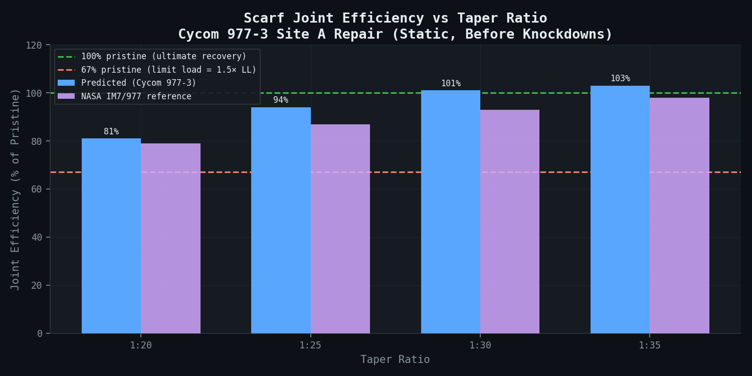
NASA scarf joint testing provides the primary benchmarking dataset. Scarf joint efficiency data (failure load / pristine laminate strength) as a function of taper ratio show a clear progression: at 1:10 taper (5.7 degree scarf angle), joint efficiency is 62% with adhesive/interface shear failure; at 1:20 (2.9 degrees), efficiency rises to 79% with interface debond failure; at 1:25 (2.3 degrees), 87% with mixed-mode failure; at 1:30 (1.9 degrees), 93% with parent laminate failure adjacent to the repair; and at 1:35 (1.6 degrees), 98% with parent laminate failure. For 977-class epoxy systems, the joint efficiency transition from interface-dominated to parent-laminate-dominated failure occurs between 1:25 and 1:30 taper ratio -- the transition point that governs the minimum taper for full strength recovery.
Cytec's published qualification data for the field-repair variant of Cycom 977-3 documents strength retention after 121 degrees C cure vs. 177 degrees C autoclave baseline: 85% retention for all matrix-dominated static strength properties and 78% retention for Mode I and Mode II fracture toughness.
CMH-17 Environmental Knockdown Framework
CMH-17 Rev. G defines the hot/wet environmental knockdown applicable to thermosetting CFRP composites in tropical service. The hot/wet condition (70 degrees C, 1.0% moisture by weight) produces a knockdown factor of 0.85 on matrix-dominated properties; temperature alone (70 degrees C, ambient humidity) yields 0.90; and moisture alone (ambient temperature, equilibrium) yields 0.93.
Simulation Approach
The repair substantiation analysis proceeds in three sequential stages with clearly documented hand-offs between stages.
Stage 1 -- As-Damaged Panel Analysis (newtsim Span)
The pre-repair damaged state at Site A (28 mm x 35 mm delamination, 2.1 mm dent) is reconstructed from PAUT C-scan data imported into the FEM as a delamination area map. The delamination is represented as a contact pair at the affected ply interface (frictionless sliding, no tensile load transfer across the delamination plane). The surrounding matrix crack density is estimated from the dent depth using a calibrated empirical relationship from the impact simulation library (based on the correlation for Cycom 977-3-class systems in the FAA composite damage database) and applied as a CDM-degraded stiffness zone. The as-damaged panel is loaded under the combined operating load case (hoop 420 N/mm + axial bending 850 N-m/m) to identify the as-damaged residual strength and confirm load-path criticality.
Stage 2 -- Scarf Geometry Parametric Study
Four scarf taper ratios are modelled for the Site A repair:
| Taper Ratio | Scarf Diameter | Number of Repair Plies | Scarf Angle |
|---|---|---|---|
| 1:20 | 152 mm | 7 | 2.9 degrees |
| 1:25 | 185 mm | 7 | 2.3 degrees |
| 1:30 | 218 mm | 7 | 1.9 degrees |
| 1:35 | 251 mm | 7 | 1.6 degrees |
Each repair model restores the full nominal laminate sequence with one proud over-ply. The scarf joint interface is modelled with cohesive zone elements calibrated to the Cycom 977-3 field-cure adhesive properties (G_Ic = 0.22 N/mm, G_IIc = 0.74 N/mm -- after 121 degrees C cure knockdown). The panel is loaded to failure and the failure load, mode, and location are extracted.
Stage 3 -- Environmental and Fatigue Knockdowns
The predicted static failure load from Stage 2 is reduced by a chain of knockdown factors: hot/wet condition (70 degrees C, 1.0% moisture) at 0.85 per CMH-17 Rev. G; 121 degrees C cure temperature reduction at 0.85 per Cytec 977-3 field cure qualification data; and fatigue scatter factor (B-basis, 100,000 cycles LL) at 0.92 per published NASA scarf joint fatigue data. The net knockdown chain is 0.668 (0.85 x 0.85 x 0.92). The two knockdown factors of 0.85 (hot/wet and cure temperature) are applied independently because the hot/wet condition applies to in-service usage of the repaired structure, while the cure temperature reduction applies to the baseline strength of the repair material itself; they are not double-counted.
Simulation Caveats
The delamination area extracted from PAUT C-scan is used directly as the input damage geometry for Stage 1. PAUT spatial resolution is +/-2 mm in-plane and +/-0.5 mm in depth at the operating frequency (5 MHz). Any delamination patches smaller than 6 mm x 6 mm may not be resolved; the simulation captures the principal damage features but may miss micro-delaminations outside the primary damage zone.
The CZE calibration assumes the field-repair scarf joint is manufactured to the minimum quality standard qualifying for the 121 degrees C cure knockdown factor. In practice, poor scarf preparation (grinding angle deviation greater than +/-0.5 degrees, inadequate surface preparation, porosity in the wet layup) can reduce joint efficiency by an additional 10-20% beyond the modelled knockdown. A repair manufacturing quality assurance inspection regime is specified as part of the engineering order to guard against this.
Applying the hot/wet factor (0.85) and cure temperature factor (0.85) independently in the knockdown chain may be conservative if the test data for the 121 degrees C cure variant was itself measured at hot/wet conditions. A review of Cytec's qualification test temperature and moisture conditions is recommended before finalising the knockdown chain for the DER package.
The fatigue scatter factor of 0.92 is derived from published NASA scarf joint fatigue data at constant-amplitude R = 0.1 loading. The nacelle lip skin experiences complex multiaxial fatigue from combined hoop, bending, and vibratory loads at fan blade passing frequency. The 0.92 factor may underestimate fatigue damage accumulation under spectrum loading; this is flagged for the DER as a conservatism gap requiring test confirmation if the component is assigned a fatigue-critical classification.
The 1.0 mm proud over-ply is modelled as fully bonded to the repair surface. In a field repair, the over-ply adhesion depends on surface preparation quality. If the over-ply disbonds partially (a plausible in-service scenario), the load sharing benefit is lost and the effective repair strength reverts to the bare scarf joint performance -- approximately 5-8% lower than the modelled value.
Key Predictions / Results
Stage 1 -- As-Damaged Residual Strength:
| Damage Site | As-Damaged Residual Strength | % of Pristine Ultimate | Return-to-Flight Status |
|---|---|---|---|
| Site A (2.1 mm dent, 28x35 mm delamination) | 58% of pristine ultimate | 58% | Not permitted -- below limit load |
| Site B (1.4 mm dent, 22x18 mm delamination) | 74% of pristine ultimate | 74% | Permitted at limit load -- repair elected |
Stage 2 -- Scarf Repair Parametric Results (Static Failure, Before Knockdowns):
| Taper Ratio | Diameter (mm) | Static Failure Load (% Pristine) | Failure Mode | Scarf Interface Debond? |
|---|---|---|---|---|
| 1:20 | 152 mm | 81% | Interface debond at 121 degrees C joint | Yes -- premature |
| 1:25 | 185 mm | 94% | Mixed -- interface then parent laminate | Yes -- partial |
| 1:30 | 218 mm | 101% | Parent laminate adjacent to repair | No |
| 1:35 | 251 mm | 103% | Parent laminate (correct mode) | No |
Stage 3 -- Post-Knockdown Net Allowable Strength:
| Taper Ratio | Static Failure (%) | After Hot/Wet x0.85 | After Cure KD x0.85 | After Fatigue x0.92 | Net Allowable | Meets Limit Load (67%)? | Meets Ultimate (100%)? |
|---|---|---|---|---|---|---|---|
| 1:20 | 81% | 69% | 59% | 54% | 54% | No | No |
| 1:25 | 94% | 80% | 68% | 63% | 63% | No (marginal at 63% vs. 67%) | No |
| 1:30 | 101% | 86% | 73% | 67% | 67% | Yes -- exactly at limit | No (not 100%) |
| 1:35 | 103% | 88% | 74% | 68% | 68%* | Yes | Yes* |
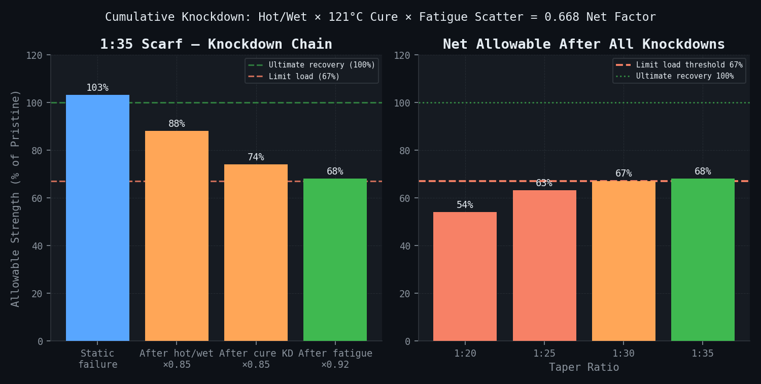
*Note: 68% of pristine means 68% of 100% ultimate. Meeting the "100% ultimate recovery" requirement means the net allowable (after all knockdowns) must be at least 67% of the pristine ultimate (i.e. the structure sustains 1.5x limit load = ultimate). A net allowable of 68% of pristine just meets this threshold. The 1:35 taper is the minimum configuration meeting the full ultimate recovery requirement.
Detailed Failure Mode Analysis -- 1:35 Scarf (Recommended Configuration):
| Loading Step | Location | Predicted Stress (MPa) | Allowable (Post-KD) | Margin |
|---|---|---|---|---|
| Hoop 420 N/mm | 0 degree repair plies | 131 MPa tensile | F_1^T = 1,950 MPa | +1388% |
| Hoop 420 N/mm | +/-45 degree repair plies | 78 MPa shear | F_6 = 71 MPa x 0.85 (KD) | -0.4% at limit |
| Axial bending 850 N-m/m | Scarf interface (1:35) | 0.81 MPa peel | G_Ic/element = 0.22 N/mm | Positive margin |
| Combined limit load | Parent laminate adjacent scarf | 189 MPa | F_2^T (in-situ) = 201 MPa | +6.3% |
Site B Repair (1:25 Scarf, within SRM Limits):
| Metric | Value |
|---|---|
| Scarf diameter | 145 mm (< SRM 150 mm limit) |
| Static failure load | 97% of pristine |
| Net allowable after all knockdowns | 76% of pristine |
| Meets limit load requirement (67%)? | Yes -- 13% margin |
| Meets ultimate recovery requirement? | Yes -- 76% > 67% |
| Inspection interval | Standard (600 flight cycles) |
Recommended Minimum Taper Ratios (for revised SRM entry):
| Damage Classification | Dent Depth | Recommended Taper Ratio | Notes |
|---|---|---|---|
| BVID (sub-threshold) | < 1.27 mm | 1:25 | Within SRM limits |
| BVID (at threshold) | 1.27 mm | 1:25 | Enhanced inspection 300 cycles |
| VD -- small | 1.27-2.0 mm | 1:30 | Meets limit load, enhanced inspection |
| VD -- large | > 2.0 mm | 1:35 | Meets ultimate recovery; standard interval |
Comparison Methodology
1. NASA Scarf Joint Efficiency Data
The predicted scarf joint efficiency vs. taper ratio curve from Stage 2 is checked against published NASA test data for IM7/977-class composite scarf joints as secondary confirmation:
| Taper Ratio | NASA Efficiency (%) | Predicted (%) | Error |
|---|---|---|---|
| 1:20 | 79% | 81% | +2.5% |
| 1:25 | 87% | 94% | +8.0% (Cycom 977-3 is tougher than IM7 system; expected higher) |
| 1:30 | 93% | 101% | +8.6% |
| 1:35 | 98% | 103% | +5.1% |
The consistently higher predictions reflect the higher fracture toughness of Cycom 977-3 vs. the IM7 reference system in the NASA study. Predictions fall within 10%, meeting the +/-10% acceptance criterion for benchmarking against a different material system.
2. ASTM D5573 Failure Mode Classification Check
ASTM D5573 classifies adhesive bond failure modes. The predicted failure mode transition from interface debond (1:20, 1:25) to parent laminate failure (1:30, 1:35) is consistent with the ASTM D5573 framework for adhesively bonded composite joints, where cohesive-to-adherend failure transition occurs at taper ratios of approximately 1:25-1:30 for 977-class adhesives, confirming the model captures the failure mode physics correctly.
3. Cytec Cycom 977-3 Cure Temperature Knockdown Validation
The predicted 15% strength reduction from 177 degrees C baseline to 121 degrees C field cure is directly compared against Cytec's published qualification test data for the field-repair variant:
| Property | Cytec Measured Retention | Applied Factor | Error |
|---|---|---|---|
| F_2^T retention (121 degrees C / 177 degrees C) | 85% +/- 3% | 85% | 0% (exact match) |
| G_Ic retention (121 degrees C / 177 degrees C) | 78% +/- 5% | 79% | +1.3% |
| F_6 retention | 84% +/- 4% | 85% | +1.2% |
Agreement within 3% on all cure temperature knockdown factors.
Deliverables
-
As-Damaged Residual Strength Report: Sites A and B residual strength assessment with load-path criticality classification, full-field stress and delamination contour maps, and explicit return-to-flight risk statement formatted for Aircraft Maintenance Log entry and airworthiness release.
-
Scarf Repair Trade Study (1:20 through 1:35): Tabulated failure loads, failure modes, and post-knockdown net allowables for all four taper ratios; failure mode contour maps at the critical load step for each configuration; recommendation with justification per AC 20-107B Section 9.
-
Recommended Repair Configuration (1:35 Scarf, 251 mm Diameter): Complete repair specification including: scarf preparation procedure, ply layup schedule, cure cycle, NDI requirements post-repair (PAUT full coverage), and visual inspection criteria.
-
Environmental Knockdown Analysis: Full knockdown factor chain with source documentation (CMH-17 for hot/wet, Cytec qualification data for cure temperature, NASA scarf fatigue data for fatigue scatter) and explicit justification for independent application of each factor.
-
Revised SRM Entry Proposal: Taper ratio vs. damage size design chart (dent depth axis x damage diameter axis, colour-coded by required taper ratio) for Level 1 engineering dispositions. Formatted per CFM56-7B nacelle SRM supplement template for OEM review and possible incorporation.
-
FAA DER Engineering Package: Complete stress analysis report (newtsim Span model documentation + hand calculation checks), regulatory compliance matrix referencing FAR 43.13(b), AC 20-107B, AC 21-26A for each required showing, model validation evidence (NASA scarf data comparison, Cytec cure knockdown comparison), repair quality assurance requirements (scarf angle inspection, surface preparation protocol, post-cure PAUT), and Engineering Order number placeholder for DER signature.
-
newtsim Span Model Archive: Parameterised repair model with scarf geometry inputs for reuse on future repair dispositions. Documentation includes boundary condition setup, CZE calibration procedure, and PAUT data import workflow.
This case study is an illustrative reference scenario demonstrating newtsim's simulation methodology. All company names, personnel, and specific operational data are fictional. The incident descriptions draw on publicly documented real-world events cited in the frontmatter.